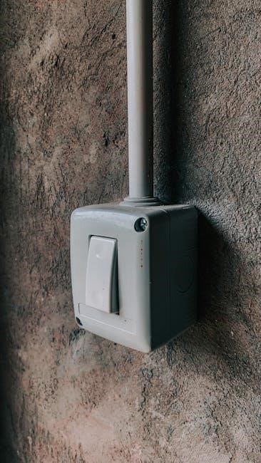
An electrical wiring diagram is a visual representation of an electrical circuit, essential for installing, troubleshooting, and understanding electrical systems. It provides a clear roadmap for connecting components safely and efficiently, ensuring compliance with electrical codes and standards. Whether for residential or commercial use, these diagrams are indispensable for electricians and DIY enthusiasts alike.
What is an Electrical Wiring Diagram?
An electrical wiring diagram is a detailed graphical representation of an electrical circuit’s components and their connections. It illustrates how wires, devices, and systems are interconnected, using standardized symbols and notations. These diagrams are essential for installing, maintaining, and troubleshooting electrical systems, providing a clear visual guide for electricians and DIY enthusiasts. They are widely used in residential, commercial, and industrial settings to ensure safe and efficient electrical connections. Understanding wiring diagrams is fundamental for working with electrical systems effectively.
Importance of Electrical Wiring Diagrams
Electrical wiring diagrams are crucial for ensuring safety, efficiency, and compliance with electrical codes. They provide a clear visual guide for installing, maintaining, and troubleshooting electrical systems. By following these diagrams, electricians can identify potential hazards and avoid dangerous connections. They also simplify complex circuits, making it easier to locate components and diagnose issues. For both professionals and DIY enthusiasts, wiring diagrams are indispensable, promoting accuracy and reducing the risk of electrical fires or system failures. Their universal understanding ensures consistency across projects, making them a fundamental tool in the electrical trade.
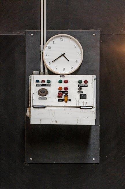
Types of Electrical Wiring Diagrams
Electrical wiring diagrams include circuit diagrams, wiring harness diagrams, and schematic diagrams, each serving specific purposes in designing, installing, and troubleshooting electrical systems with precision and clarity.
Circuit Diagrams
Circuit diagrams are detailed visual representations of electrical circuits, showcasing all components and their connections. They use standardized symbols to depict devices like switches, outlets, and wires, ensuring clarity. These diagrams are essential for understanding circuit operation, troubleshooting, and making modifications. By illustrating the flow of electricity, they help electricians and DIYers identify potential issues and ensure safe installations. Circuit diagrams are fundamental for both simple and complex systems, making them indispensable in residential and commercial electrical work.
Wiring Harness Diagrams
Wiring harness diagrams illustrate the layout and connections of wires, connectors, and components in an electrical system. They simplify complex setups by detailing how wires are bundled and routed. These diagrams are crucial for manufacturing, troubleshooting, and repairs, as they provide a clear visual guide. By using color coding and standardized symbols, wiring harness diagrams ensure that technicians can quickly identify and resolve issues. They are particularly essential in automotive and industrial applications, where multiple components rely on precise wiring connections. These diagrams are vital for maintaining system efficiency and reliability in technical projects.
Schematic Diagrams
Schematic diagrams are detailed representations of electrical circuits, focusing on the logical connections between components. They use standardized symbols and lines to depict wiring, devices, and their interactions. These diagrams prioritize clarity over physical layout, making them ideal for designing, troubleshooting, and understanding complex systems. Schematics are widely used in both residential and commercial electrical work, serving as a blueprint for installing and repairing circuits. Their simplified format allows electricians and engineers to quickly identify components and trace signal flows, ensuring efficient problem-solving and system maintenance.
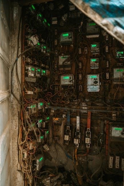
Components of an Electrical Wiring Diagram
An electrical wiring diagram consists of wires, circuits, devices, and connections, providing a clear visual guide for installing and troubleshooting electrical systems. It includes symbols, labels, and annotations to ensure safety and efficiency, helping users understand the flow of electricity and the relationships between components. These diagrams are essential for both residential and commercial electrical work, ensuring systems are wired correctly and safely.
Symbols and Notations
Symbols and notations are essential elements in electrical wiring diagrams, representing components like switches, outlets, and transformers. Standardized symbols, often defined by organizations like the International Electrotechnical Commission (IEC), ensure clarity and consistency. These symbols act as a universal language, allowing electricians to quickly identify and understand circuit elements. Common symbols include those for resistors, capacitors, and inductors, each with specific notations to denote ratings and connections. Proper use of these symbols ensures accurate circuit interpretation, making them indispensable for safe and efficient electrical work.
Color Coding in Wiring Diagrams
Color coding in wiring diagrams is a critical system that ensures safety and clarity. Different colors represent specific types of wires, such as live, neutral, and ground. For example, black wires typically denote live wires, while white indicates neutral. Green or green-and-yellow-striped wires are reserved for grounding. This standardized system helps electricians quickly identify wire functions, reducing the risk of errors. Proper color coding is essential for maintaining safety and ensuring compliance with electrical codes. It simplifies troubleshooting and makes diagrams universally understandable, even across languages and regions.
Labels and Annotations
Labels and annotations are essential elements in wiring diagrams, providing clear identification of components, connections, and circuit functions. They ensure that every wire, terminal, and device is easily recognizable, reducing confusion and enhancing safety. Proper labeling helps technicians trace circuits efficiently and understand the purpose of each connection. Annotations often include notes, warnings, and specifications, offering additional context. Together, they make diagrams more accessible, ensuring that even complex systems can be understood and worked on safely and effectively by professionals and DIYers alike.

Understanding Electrical Basics
Understanding electrical basics is crucial for interpreting wiring diagrams. It involves grasping fundamental principles like voltage, current, and resistance, ensuring safe and effective electrical system installations.
Voltage, Current, and Resistance
Voltage, current, and resistance are fundamental concepts in understanding electrical systems. Voltage is the potential difference driving electric charge, while current is the rate of charge flow. Resistance opposes this flow, influenced by material and wire length. Ohm’s Law (V=IR) relates these quantities, essential for circuit analysis. These principles are crucial for interpreting wiring diagrams, ensuring safe and efficient electrical connections. Understanding them helps in troubleshooting and designing circuits effectively, whether for residential or commercial applications.
Ohm’s Law and Its Applications
Ohm’s Law states that current (I) equals voltage (V) divided by resistance (R), expressed as I = V/R. This fundamental principle helps calculate unknown values in circuits, ensuring safety and efficiency. It’s widely used in wiring diagrams to determine appropriate wire gauges, circuit breakers, and resistor values. By applying Ohm’s Law, electricians can troubleshoot issues, design circuits, and maintain electrical systems effectively, making it a cornerstone of electrical engineering and a key tool for interpreting wiring diagrams accurately.
Electrical Safety Tips
Always turn off the power supply before working on any electrical system to prevent shocks or injuries. Use a multimeter to verify the circuit is de-energized. Wear appropriate personal protective equipment (PPE), such as insulated gloves and safety glasses. Never touch electrical components with wet hands or while standing in water. Avoid overloading circuits to prevent fires. Ensure all connections are secure and meet local electrical codes. Keep work areas well-lit and clear of flammable materials. Follow wiring diagrams carefully and consult professionals if unsure.
Residential Wiring Basics
Residential wiring involves installing and maintaining electrical systems in homes. It includes understanding circuits, outlets, and switches, ensuring safe and efficient power distribution throughout the house.
Types of Residential Wiring
Residential wiring includes various types such as Non-Metallic Sheathed Cable (NM), Underground Feeder (UF), and armored cable. NM is the most common, used for interior walls, while UF is suitable for outdoor and underground installations. Armored cable offers enhanced protection in high-traffic areas. Each type ensures safe and reliable electrical connections, catering to specific needs and environments within a home. Proper selection is crucial for compliance with electrical codes and long-term system performance.
Common Residential Circuits
Residential electrical systems typically include branch circuits for lighting, outlets, and appliances. Dedicated circuits are required for high-power devices like electric dryers and air conditioning units. Ground Fault Circuit Interrupters (GFCI) protect areas near water, such as kitchens and bathrooms, while Arc Fault Circuit Interrupters (AFCI) prevent fires caused by faulty wiring. Additionally, 240-volt circuits are used for large appliances like water heaters and electric ranges. Proper installation and organization of these circuits ensure safety, efficiency, and compliance with electrical codes.
Ground Fault Circuit Interrupters (GFCI)
GFCI outlets are essential safety devices in residential wiring, protecting against ground faults by interrupting the circuit when a leak is detected. They are required in areas near water, such as kitchens, bathrooms, and outdoor spaces, to prevent electrical shocks. GFCI devices quickly disconnect power, reducing the risk of injury or fire. Their proper installation, as shown in wiring diagrams, ensures compliance with safety standards and provides reliable protection in hazardous environments, making them a critical component of modern electrical systems.
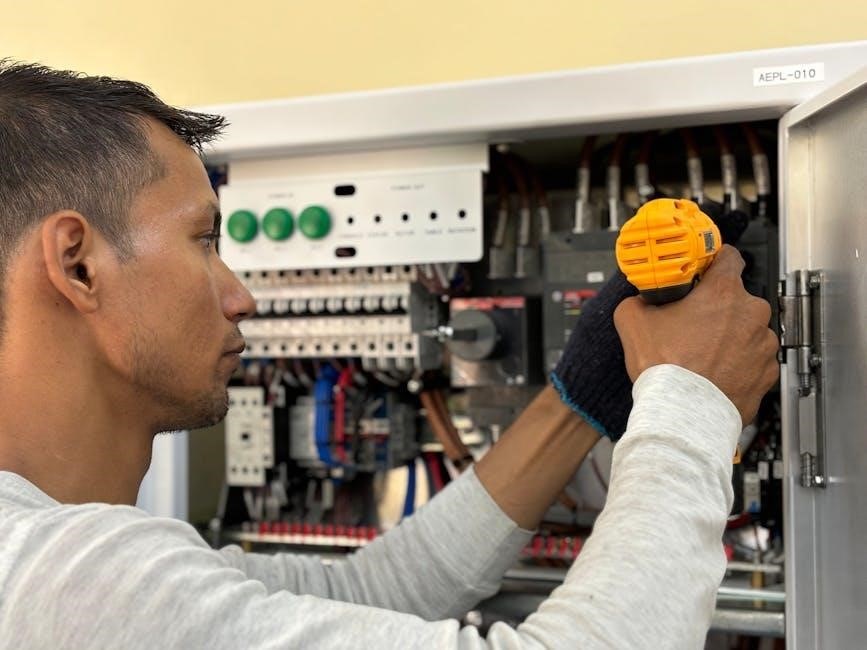
Commercial Wiring Basics
Commercial wiring involves complex electrical systems designed for high power demands, often utilizing three-phase systems and robust infrastructure to support industrial and business operations efficiently and safely.
Types of Commercial Wiring
Commercial wiring includes various systems tailored to meet high power demands. Three-phase wiring is common for heavy machinery and industrial applications, offering efficient power distribution. Armored cable is used in harsh environments for protection, while conduit wiring provides flexibility and safety. Bus duct systems are employed for large-scale power distribution in commercial buildings; Each type ensures reliable electrical connections, supporting the unique needs of businesses and industries. Proper installation and maintenance are crucial for safety and efficiency in commercial settings.
Three-Phase Electrical Systems
A three-phase electrical system is a common configuration for commercial and industrial applications, offering efficient power distribution. It consists of three live wires carrying alternating currents at 120-degree phase differences. This setup reduces conductor size and increases power transmission efficiency. Three-phase systems are ideal for powering heavy machinery and large loads, ensuring balanced current flow. They are widely used in factories, data centers, and high-rise buildings due to their reliability and energy-saving capabilities. Proper wiring diagrams are essential for safe and effective installation.
Troubleshooting Electrical Wiring
Troubleshooting electrical wiring involves identifying issues like short circuits, open circuits, or faulty connections. Using tools such as multimeters and circuit diagrams helps diagnose and resolve problems efficiently.
Common Electrical Wiring Issues
Common electrical wiring issues include short circuits, overloaded circuits, and faulty connections. These problems often arise from improper installation, worn-out wires, or excessive current demand. Short circuits occur when wires touching incorrectly cause a surge, potentially damaging equipment. Overloaded circuits can lead to overheating, increasing fire risks. Faulty connections may result in intermittent power or complete outages. Identifying these issues early is crucial to ensure safety and prevent further damage to electrical systems. Regular inspections and adherence to wiring standards help mitigate these risks effectively.
Using a Multimeter for Diagnosis
A multimeter is an essential tool for diagnosing electrical wiring issues. It measures voltage, current, and resistance, helping identify faults like short circuits or open connections. By setting the multimeter to the correct function, you can test wires, outlets, and components. For example, measuring voltage ensures power is present, while checking resistance helps detect short circuits or open wires. Always use the appropriate range for accurate readings and ensure safety by turning off power before testing. Proper multimeter use is key to effective troubleshooting and ensuring electrical system reliability.
Circuit Breakers and Fuses
Circuit breakers and fuses are critical components in electrical systems, designed to protect against overcurrent conditions. Fuses melt when excessive current flows, interrupting the circuit, while circuit breakers trip and can be reset. Both prevent damage from short circuits or overloads, ensuring safety and maintaining electrical flow. Understanding their operation is vital for troubleshooting, as they indicate potential issues in wiring or connected devices. Proper use and maintenance of these devices are essential for reliable and safe electrical system performance.

Electrical Safety and Best Practices
Adhering to safety protocols is crucial when working with electrical systems. Always de-energize circuits, use proper PPE, and test tools before use to ensure a safe working environment.
Safety Protocols for Electrical Work
Strict adherence to safety protocols is essential in electrical work to prevent accidents. Always disconnect power sources and verify de-energization using a multimeter. Wear appropriate PPE, including insulated gloves and safety glasses, to protect against shocks and arc flashes. Ensure all tools are properly insulated and rated for the voltage being worked with. Never work on live circuits, and always follow lockout/tagout procedures to ensure circuits remain de-energized during maintenance or repairs. Regular training and updates on safety standards are vital to maintaining a safe working environment.
Personal Protective Equipment (PPE)
Personal Protective Equipment (PPE) is essential for safeguarding against electrical hazards. Insulated gloves prevent shock, while safety glasses protect eyes from debris. Steel-toe boots and hard hats shield against physical injuries. Fire-resistant clothing minimizes risks from arc flashes. Ensure all PPE meets industry standards and is regularly inspected for wear. Proper use of PPE significantly reduces the risk of electrical-related injuries, making it a critical component of electrical safety protocols. Always prioritize PPE to create a safer working environment for all electrical tasks.
Emergency Procedures
In case of an electrical emergency, stay calm and act quickly. For electrical shocks, immediately disconnect the power source and avoid direct contact with live wires. Use non-conductive tools to ensure safety. If an electrical fire occurs, use a fire extinguisher rated for electrical fires (CO2 or dry chemical). Evacuate the area, warn others, and call emergency services. For power outages, switch off appliances to prevent damage from power surges. Always prioritize calling professionals for severe electrical issues to ensure safety and proper resolution.
Resources for Learning Electrical Wiring
Explore resources like Electrical 101 books, online courses, and the 101 Electrical Wiring Diagram user manual for comprehensive guides and hands-on learning experiences in electrical wiring.
Recommended Tools for Electrical Work
Essential tools for electrical work include multimeters, wire cutters, screwdrivers, pliers, and safety gear like gloves and goggles. A multimeter measures voltage, current, and resistance, ensuring circuit safety. Wire cutters and strippers are crucial for preparing cables, while screwdrivers handle connections. Pliers aid in bending wires, and a voltage tester verifies live circuits. Additionally, a wiring diagram guide, like the 101 Electrical Wiring Diagram, provides clear instructions for various projects, helping professionals and DIYers alike complete tasks efficiently and safely.
Books and Online Courses
For comprehensive learning, books like Electrical 101 and online courses offer in-depth knowledge. The book covers fundamentals, circuit analysis, and safety practices, while online platforms provide interactive tutorials and hands-on projects. Courses like Electrical 101 on YouTube and specialized websites focus on voltage basics, wiring techniques, and troubleshooting. These resources cater to both beginners and professionals, ensuring a well-rounded understanding of electrical systems and wiring diagrams. They complement the 101 Electrical Wiring Diagram PDF, enhancing practical and theoretical skills effectively.
Professional Certifications
Professional certifications are essential for validating expertise in electrical wiring. Certifications like NEC (National Electric Code) compliance ensure adherence to safety standards. Organizations such as NEMA and UL offer certifications that verify proficiency in handling electrical systems. These credentials are crucial for electricians and technicians, demonstrating their ability to work safely and efficiently. By obtaining these certifications, professionals can stay updated with industry standards and best practices, ensuring reliable and compliant electrical work. They complement the knowledge gained from resources like the 101 Electrical Wiring Diagram PDF, enhancing career prospects and trustworthiness in the field.
Understanding electrical wiring diagrams is crucial for safe and efficient installations. By mastering these diagrams, individuals can ensure compliance with safety standards and achieve reliable results.
Electrical wiring diagrams are essential tools for understanding and working with electrical systems. They provide visual representations of circuits, components, and connections, ensuring safe installations. Key elements include symbols, color coding, and labels, which simplify troubleshooting and maintenance. Adhering to safety protocols and using proper tools is crucial. These diagrams are invaluable for both professionals and DIY enthusiasts, offering clear guidance for compliance with electrical standards. Mastery of wiring diagrams enhances efficiency and ensures reliable electrical system performance.
Final Thoughts and Next Steps
Mastering electrical wiring diagrams is a foundational skill for anyone working with electrical systems. By understanding these diagrams, individuals can ensure safe and efficient installations. Start with simple projects to apply your knowledge, gradually tackling more complex circuits. Invest in quality tools like multimeters and circuit testers to enhance your work. Consider enrolling in courses or consulting detailed guides to deepen your understanding. Remember, electrical work requires precision and caution, so always follow safety protocols to avoid hazards;
Frequently Asked Questions (FAQs)
Q: What is the best way to read an electrical wiring diagram?
A: Start by identifying the components and their symbols, then follow the flow of the circuit to understand how they connect.
Q: What tools are essential for electrical work?
A: A multimeter, wire strippers, pliers, and circuit testers are must-haves for safe and efficient electrical troubleshooting and installations.
Q: How can I ensure electrical safety while working on a circuit?
A: Always disconnect the power source, use proper PPE, and verify voltage levels before starting any electrical work.
Q: Where can I find reliable resources to learn electrical wiring?
A: Consider enrolling in online courses, consulting certified manuals, or joining professional forums for guidance and support.
