Categories
Manuals

sig p320 manual safety cut template

Sig P320 Manual Safety Cut Template: A Comprehensive Guide

Navigating the complexities of Sig P320 manual safety modifications requires precision and knowledge. This guide details templates, tools, and techniques
for converting grip modules, ensuring compliance and functionality, alongside crucial safety considerations for a successful outcome.

Understanding the Need for Manual Safety Cuts

The necessity for manual safety cuts on Sig P320 grip modules primarily stems from legal requirements, particularly in states like California. These regulations mandate a manual safety lever for certain pistol configurations to be considered compliant. Originally, many P320 models were manufactured without this feature, necessitating modifications for legal ownership in restricted jurisdictions.

Beyond legal compliance, some shooters simply prefer the added control and peace of mind offered by a manual safety. It provides an extra layer of security against accidental discharge, appealing to those prioritizing enhanced firearm safety. The process involves carefully creating a cutout in the grip module to accommodate the safety lever, requiring precision and the correct tools. Understanding the specific model of P320 – standard, X-Series, or others – is crucial, as compatibility and cutout locations vary.

California Compliance and Manual Safeties

California’s stringent firearm laws necessitate manual safeties on many pistol models, including the Sig P320, to meet state compliance standards. Without a manual safety, P320s are often restricted from sale or legal ownership within California. This drives the demand for grip module modifications, enabling existing pistols to adhere to these regulations.

The requirement focuses on providing a positive mechanical safety, preventing unintentional discharge. Converting a P320 to include a manual safety involves precise cutting of the grip module to house the safety lever and associated components. Several kits and templates, like those from Sig Mechanics and Desert Depot Arms, are specifically designed to facilitate this process accurately. Ensuring the modification is performed correctly is vital for both legal compliance and safe firearm operation.

Identifying Non-Manual Safety P320 Models

Determining whether your Sig P320 requires a manual safety cutout is the first step in the conversion process. Earlier P320 models, and those manufactured for states without specific safety requirements, typically lack the necessary space within the grip module for a manual safety lever. These are the firearms needing modification for compliance in places like California.

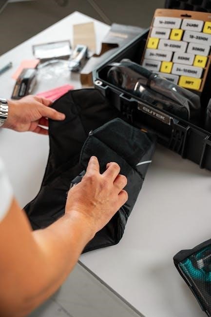
Visually, non-manual safety P320s will not have a pre-existing cutout on the left side of the grip module where the safety lever would reside. Newer grip modules may arrive with the cutout already marked, simplifying the process. However, verifying the frame’s internal components is crucial; a non-manual safety FCU (Fire Control Unit) necessitates the grip module modification. Careful inspection avoids unnecessary work and ensures compatibility with the chosen safety kit.

Tools and Kits for Manual Safety Conversion

Several specialized kits and tools facilitate accurate P320 manual safety conversions. Options include the Sig Mechanics Kit, Sig80 bit kits, Desert Depot Arms’ MSAFE-T, and WCC3D Solutions.

Sig Mechanics Kit (MSAFE-T) – Overview

The Sig Mechanics Kit, designated MSAFE-T, is widely regarded as a premium solution for P320 manual safety conversions. As highlighted in community discussions on Reddit’s r/P320, this kit stands out due to its robust metal guide construction, ensuring precision and ease of use during the cutting process.

Unlike some alternatives, the MSAFE-T isn’t simply a template; it’s a complete system designed to guide cutting tools accurately. It’s specifically engineered to convert non-manual safety P320 Fire Control Units (FCUs) to accommodate a factory ambidextrous manual safety assembly.

Furthermore, the kit includes a dedicated template for modifying Sig P320 grip modules, including both standard and X-Series variants. Available directly from Sigmech.store, the MSAFE-T is a popular choice for both professional gunsmiths and experienced DIY enthusiasts seeking a reliable and accurate conversion method.

Sig80 Bit Kit for P320 Manual Safety Conversion

The Sig80 Bit Kit offers a comprehensive solution for converting non-manual safety P320 frames to accept an ambidextrous factory manual safety. Sig80bitkitS.com explicitly states the kit’s purpose: to enable the functionality of a manual safety on previously incompatible FCUs. This is achieved through a carefully designed set of templates and specialized tools.

This kit isn’t limited to the FCU; it also provides a jig and template specifically for modifying Sig P320 grip modules. Whether you have a standard or X-Series grip module, the Sig80 kit aims to simplify the conversion process.

The kit’s design focuses on providing users with the necessary components for accurate cuts, reducing the risk of errors and ensuring a proper fit for the manual safety components. It’s a popular option for those seeking a dedicated kit for this specific modification.

Desert Depot Arms MSAFE-T Kit – Features

Desert Depot Arms’ MSAFE-T kit is engineered as a complete system for converting non-manual safety P320 FCUs to accommodate a factory manual safety assembly; Like the Sig80 kit, it centers around providing all the necessary tools for a successful conversion, streamlining the process for gun owners.

A key feature of the MSAFE-T is its inclusion of a dedicated template designed specifically for modifying X-Series grip modules. This addresses a common need for those upgrading or converting X-Series pistols to include a manual safety;

Desert Depot Arms emphasizes that the kit contains templates and tools, suggesting a more holistic approach to the conversion. This implies a focus on both accurate marking and efficient material removal during the modification process, ensuring a precise fit.

WCC3D Solutions – Alternative Cutting Methods

WCC3D offers a compelling alternative to the traditional Dremel-based approach for cutting manual safety slots in Sig P320 grip modules. Their solutions cater to those seeking methods beyond rotary tools, potentially offering increased precision and reduced risk of damaging the grip module.

While specific details of their methods aren’t fully detailed in the provided information, WCC3D’s website (wcc3d.chainmaildude.com) is presented as a resource for further exploration. This suggests they may offer specialized jigs, templates, or even machining services to facilitate the conversion.

The YouTube video referenced implies a viable method exists for cutting these slots without a Dremel, appealing to users who may lack experience with such tools or prefer a different workflow. This positions WCC3D as a provider of innovative solutions for P320 modifications.

The Cutting Process: A Step-by-Step Approach

Precise execution is vital when modifying your P320 grip module. This involves careful marking, template utilization, and controlled cutting techniques to achieve a functional safety slot.

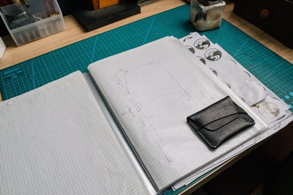
Marking the Cutout Location

Accurate marking is the foundation of a successful P320 manual safety cut. Begin by carefully referencing the template provided with your chosen kit – Sig Mechanics Kit (MSAFE-T) or Sig80 Bit Kit are popular choices. Northeastshooters.com forums suggest some newer grip modules may have pre-marked areas, but verification is crucial.

Utilize a fine-tipped marker to trace the template’s outline onto the grip module. Double-check alignment, ensuring the cutout will properly accommodate the manual safety lever. Precision here minimizes the risk of errors during the cutting phase. Some users recommend multiple light passes with the marker rather than a single, heavy line, allowing for adjustments if needed. Remember, a slightly off-center mark can lead to functional issues, so take your time and prioritize accuracy during this initial step.

Using Templates for Accurate Cuts

Templates are paramount for achieving precise and repeatable cuts on your P320 grip module. The Sig Mechanics Kit (MSAFE-T) stands out, being described as a robust metal guide, simplifying the process significantly. These templates securely attach to the grip module, guiding your cutting tool along the correct path.

Ensure the template is firmly seated and properly aligned before commencing any cutting. Clamping the template in place can further enhance stability. When using a Dremel or other rotary tool, follow the template’s contours closely, taking shallow passes to avoid overheating or damaging the grip module. WCC3D Solutions also offers alternative cutting methods, potentially utilizing their own template designs. Consistent template use guarantees a clean, functional safety cutout.

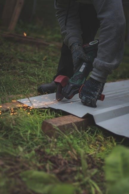
Aluminum Grip Module Cutting Techniques

Cutting aluminum grip modules demands a methodical approach, differing from polymer variants. Utilizing a Dremel is common, but requires careful control to prevent melting or excessive material removal. Employing lower speeds and frequent, shallow passes is crucial. Lubrication, such as cutting oil, can dissipate heat and improve the cut quality.

The Sig Mechanics Kit is particularly effective with aluminum, providing a stable guide. Alternatively, consider specialized rotary bits designed for aluminum. Deburring tools are essential post-cut to remove sharp edges and ensure smooth safety operation. Patience is key; rushing can lead to inaccuracies. Always prioritize safety, wearing appropriate eye protection and ensuring adequate ventilation during the cutting process.

Cutting with a Dremel – Considerations

Employing a Dremel for P320 safety cuts requires finesse and awareness of its limitations. High speeds can melt the polymer or aluminum, leading to uneven cuts and potential damage. Opt for lower speed settings and utilize various bits – sanding drums for initial material removal, and cutting wheels for precise shaping.

Consistent, light passes are paramount, avoiding deep dives that increase the risk of errors. Templates are invaluable for guiding the Dremel and ensuring accuracy. Secure the grip module firmly to prevent movement during cutting. Remember to wear eye protection and a respirator to shield against debris. Practice on scrap material first to gain proficiency before tackling the actual grip module.

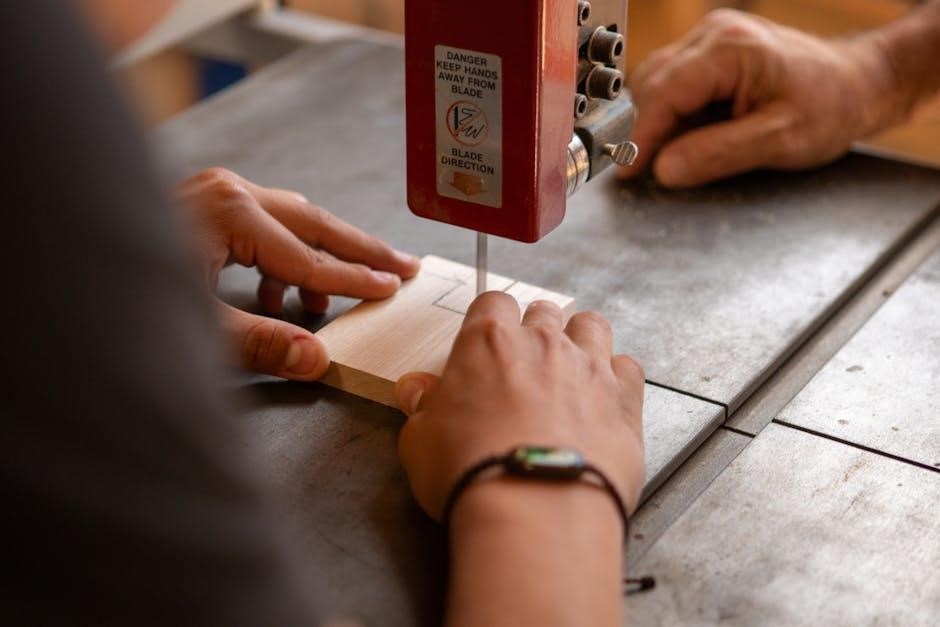
Alternative Cutting Tools (Beyond Dremel)

While Dremels are popular, alternative tools offer precision and control for P320 safety cuts. WCC3D Solutions provides specialized cutting methods, potentially involving routers or mills for cleaner, more accurate results. These methods often require more setup and skill but minimize the risk of melting or damaging the grip module.

Hand files and small saws can also be employed, though they demand significant patience and a steady hand. The Sig Mechanics Kit (MSAFE-T) utilizes a metal guide, offering a robust and easy-to-use alternative to freehand cutting. Consider your skill level and desired precision when selecting a tool; each option presents unique advantages and challenges for this modification.

Grip Module Compatibility

Understanding grip module variations is crucial for successful safety cuts. Small, medium, and large modules require specific attention, as do X-Series and standard options.

Small, Medium, and Large Grip Modules

Adapting manual safeties to different Sig P320 grip module sizes demands careful consideration. Users on Northeastshooters.com highlight that smaller grip modules, particularly the “small” size, can significantly improve fit for those with smaller hands, making the modification worthwhile. However, the cutout location remains consistent across sizes, meaning the same templates and tools generally apply.

Regardless of whether you’re working with a small, medium, or large frame, precision is paramount. The Sig Mechanics Kit (MSAFE-T) is frequently recommended as a robust and easy-to-use metal guide, ensuring accurate cuts. It’s important to note that the fundamental process doesn’t drastically change based on grip module size; the focus remains on accurately transferring the template’s outline onto the aluminum grip module.

Always double-check compatibility and ensure the chosen kit supports the specific grip module size you are modifying. Proper alignment and careful execution are key to achieving a functional and safe manual safety.

X-Series Grip Module Conversion

Converting Sig P320 X-Series grip modules to accommodate a manual safety presents unique considerations. The Desert Depot Arms MSAFE-T kit specifically includes a template designed for X-Series modules, acknowledging their distinct design. Reddit users confirm this kit’s effectiveness for X-carry grip modules, a common X-Series variant requiring the cutout for California compliance.

The X-Series often necessitates the modification due to its original design lacking the safety cutout. Utilizing the correct template is crucial; attempting to use a standard grip module template on an X-Series module will likely result in an inaccurate and unusable modification.

Careful attention to detail and precise cutting are essential, as the X-Series frame geometry differs. The MSAFE-T kit’s dedicated template streamlines this process, ensuring a proper fit for the manual safety components.

Standard Grip Module Modification

Modifying standard Sig P320 grip modules for manual safety requires precision and the appropriate tools. The Sig Mechanics Kit (MSAFE-T) is widely recommended as a robust and user-friendly solution, featuring a metal guide for accurate cuts. Sig80 Bit Kit also provides templates specifically for standard grip modules, enabling conversion of non-manual safety FCUs.

Users on Northeastshooters.com discuss marking the cutout location, with the availability of newer grip modules already featuring pre-marked areas simplifying the process. However, for older modules, careful measurement and template utilization are vital.

Achieving a smooth and functional safety operation hinges on precise cutting, avoiding damage to the frame during the modification process. A steady hand and appropriate cutting tools are paramount for a successful conversion.

Safety Considerations During Modification

Prioritize safety with eye protection and adequate ventilation during cutting. Handle tools correctly, avoiding frame damage, and ensure a controlled, precise modification process.

Eye Protection and Ventilation

When undertaking the Sig P320 manual safety cut, prioritizing personal safety is paramount. The cutting process, particularly when utilizing tools like a Dremel, generates particulate matter – tiny plastic shavings and metal fragments – that pose a significant risk to your eyes. Always wear ANSI-approved safety glasses or goggles to shield your eyes from these projectiles.

Beyond eye protection, adequate ventilation is crucial. Cutting polymers and aluminum can release fumes and dust that, while often minimal, are best avoided through inhalation. Work in a well-ventilated area, or consider using a respirator, especially during prolonged cutting sessions. A dust collection system connected to your cutting tool can further minimize airborne particles.

Remember, a safe workspace is a productive workspace. Taking these simple precautions will help ensure a smooth and injury-free modification process, allowing you to focus on achieving a precise and functional manual safety cut.

Proper Tool Handling

Successfully executing a Sig P320 manual safety cut demands meticulous tool handling. Whether employing a Dremel, rotary tool, or specialized jig, understanding your equipment is vital. Securely mount the grip module to a stable surface to prevent movement during cutting. Always unplug power tools before making adjustments or changing bits.

When using a Dremel, start with a low speed and gradually increase it as needed. Avoid applying excessive pressure, allowing the tool to do the work. Maintain a firm, controlled grip, and be mindful of the cord’s position to prevent accidental entanglement. If utilizing a template, ensure it’s firmly affixed to the grip module before commencing the cut.

Remember, improper tool handling can lead to inaccurate cuts, damage to the grip module, and potential injury. Prioritize control, stability, and a thorough understanding of your chosen tools.

Avoiding Damage to the Frame

Protecting the P320’s frame during manual safety cuts is paramount. The frame houses critical components, and any damage can compromise firearm functionality and safety. Exercise extreme caution when working near the frame rails and trigger housing. Utilize templates precisely to define the cutout area, minimizing the risk of overcutting.

When using a Dremel or similar tool, maintain a safe distance from the frame. Employ shallow passes, gradually removing material to avoid accidental contact. Regularly inspect the frame for any signs of stress or damage. If using a jig, ensure it’s properly aligned and secured to prevent slippage.

Remember, a damaged frame can necessitate costly repairs or even render the firearm unusable. Prioritize precision, control, and a conservative approach to safeguard the integrity of your P320.

Post-Cut Inspection and Functionality

Thoroughly inspect the cut for smoothness and proper safety engagement. Verify the safety lever operates correctly, ensuring positive lockup and seamless functionality after modification.

Checking for Smooth Safety Operation

After completing the manual safety cut, meticulous testing is paramount. Begin by visually inspecting the cutout, ensuring there are no burrs or sharp edges that could impede the safety lever’s movement. Carefully engage and disengage the safety several times, observing its travel and feeling for any resistance.

The lever should transition smoothly between the “safe” and “fire” positions with a distinct tactile click. Any gritty or hesitant movement indicates a potential issue requiring attention. Pay close attention to the lever’s interaction with the frame; it must not bind or rub against any internal components.

Ensure the safety consistently returns to the correct position after each manipulation. A properly executed cut allows for effortless and reliable operation, crucial for safe handling and compliance. If issues persist, re-evaluate the cutout and address any imperfections before proceeding.

Ensuring Proper Lockup

Critical to safe operation, verifying proper lockup of the safety mechanism is essential. With the safety engaged, attempt to pull the trigger. It should exhibit a firm, positive resistance and not allow the striker to release. This confirms the safety is effectively blocking the firing mechanism. Repeat this test multiple times to ensure consistent functionality.

Disengage the safety and verify the trigger functions normally, allowing for a clean and crisp pull. Any interference or altered trigger feel suggests a problem with the cut or safety installation. Inspect the safety lever’s engagement points within the frame, confirming full and secure contact when activated.

A successful modification guarantees the safety reliably prevents unintended discharge while permitting intended firing when disengaged, safeguarding the operator and bystanders.

Test Firing and Verification

Following installation, rigorous test firing is paramount to validate the modification’s success. Employ snap caps during initial testing to avoid damaging the firing pin. Cycle the action repeatedly, engaging and disengaging the manual safety to confirm smooth operation without interference. Ensure the safety lever clicks positively into each position.

Proceed to live fire testing in a safe and controlled environment, adhering to all firearm safety rules. Begin with a small number of rounds, carefully observing for any malfunctions or unexpected behavior. Verify the safety consistently prevents discharge when engaged and allows for normal firing when disengaged.

Document all test results and address any issues immediately. A successful test confirms a safe and functional manual safety conversion.

Resources and Further Information

Explore online forums like Northeastshooters.com and Reddit’s r/P320 for user experiences and recommendations. WCC3D Solutions provides additional resources and cutting methods.

Northeastshooters.com Forums – User Experiences

Northeastshooters.com provides a valuable platform for firsthand accounts regarding P320 manual safety cuts. Users frequently discuss their experiences ordering frames directly from Sig Sauer, noting that smaller grip modules can significantly improve fit for those with smaller hands. A common question revolves around marking the cutout location, with some members reporting encountering newer grip modules already pre-marked for safety installation.

Discussions highlight the importance of accurate marking and the tools used to achieve it. While specific methods vary, the forum serves as a repository of practical advice. Members share insights on challenges encountered and solutions implemented during the modification process, offering a collaborative environment for troubleshooting and learning. The date of a relevant post from 2017 shows ongoing interest in this topic, and recent activity confirms continued relevance.

Reddit r/P320 – Community Recommendations

The r/P320 subreddit consistently recommends the Sig Mechanics Kit (MSAFE-T) as the premier solution for P320 manual safety template cuts. Users praise its robust metal guide construction and ease of use, emphasizing its effectiveness even for those new to firearm modifications. Several members have reported successful aluminum grip module cuts using this kit, highlighting its reliability and precision.

The community frequently addresses California compliance concerns, with the manual safety conversion being a key requirement. Discussions often center around the X-Carry grip module, necessitating a cutout for proper functionality. The Sig Mechanics Kit is repeatedly cited as the best option available, with a direct link to sigmech.store provided for convenient access. Recent posts from November 2024 demonstrate the continued relevance of this recommendation.

WCC3D Website – Additional Resources

WCC3D Solutions presents itself as a viable alternative for Sig P320 manual safety slot cutting, particularly for those seeking methods beyond the traditional Dremel approach. Their website, chainmaildude.com, offers resources and potentially different cutting techniques, catering to users who may prefer options outside of dedicated jig kits.

While the provided information doesn’t detail specific template offerings, WCC3D’s presence suggests a focus on providing solutions for grip module modification. A YouTube video linked from their site demonstrates the process of cutting manual safety slots, implying a level of expertise and practical guidance. The website is positioned as a source for tools and information related to this modification, offering a potential pathway for DIY enthusiasts.

Categories
Manuals

ram 1500 manual

Ram 1500 Manual: A Comprehensive Guide

This guide serves as your definitive resource for the Ram 1500, encompassing everything from initial setup to detailed maintenance procedures and safety protocols.

Welcome! This manual is meticulously crafted to be your primary companion in understanding and maximizing the capabilities of your Ram 1500. Whether you’re a first-time owner or a seasoned truck enthusiast, this resource provides essential information regarding operation, maintenance, and safety features.

Before operating your vehicle, we strongly recommend thoroughly reviewing this manual. It details everything from basic controls and driving techniques to complex systems like Uconnect and advanced driver-assistance technologies. Understanding these aspects will ensure a safe, enjoyable, and efficient driving experience.

This guide also serves as a valuable reference for routine maintenance, troubleshooting common issues, and interpreting warning lights. Proper maintenance, as outlined within, is crucial for preserving your Ram 1500’s performance and longevity. Consider this manual an investment in your vehicle’s future.

Understanding Your Vehicle’s Documentation

Your Ram 1500 arrives with a suite of documentation designed to support your ownership experience. Beyond this primary Owner’s Manual, you’ll find supplemental materials covering specific features and systems. These include a separate guide for the Uconnect infotainment system, detailing its functionalities and customization options.

It’s vital to familiarize yourself with all provided literature. Warranty information outlines your vehicle’s coverage, while the roadside assistance guide details available services in case of emergencies. Keep these documents readily accessible within the vehicle for quick reference.

Remember that manuals may be updated periodically to reflect changes or improvements. Digital versions are often available online, offering the most current information. Regularly checking for updates ensures you have the latest guidance for your Ram 1500. Proper understanding of these resources empowers you as a vehicle owner.

Vehicle Overview & Key Features

This section details the Ram 1500’s architecture, encompassing model year variations, available trim levels, and a comprehensive exploration of its core engine and drivetrain options.

Ram 1500 Model Years Covered by Manuals

Ram 1500 owner’s manuals are meticulously crafted to support a broad spectrum of model years, ensuring owners have access to relevant information throughout their vehicle’s lifespan. While specific availability may vary, comprehensive manuals generally cover models from the late 1990s through the current year.

Early generation manuals (1994-2002) focus on simpler mechanical systems, while later editions (2003-2018) incorporate increasingly complex electronic features. The fourth generation (2019-present) manuals detail advanced technologies like the Uconnect infotainment system and various driver-assistance features.

It’s crucial to note that significant design changes between model years necessitate using the manual specifically corresponding to your vehicle’s production date. Accessing the correct manual guarantees accurate guidance on operation, maintenance, and safety procedures tailored to your Ram 1500’s unique configuration.

Trim Levels and Their Specific Manuals (e.g., Tradesman, Laramie)

Ram 1500 trim levels – Tradesman, Big Horn/Lone Star, Laramie, Rebel, Limited, and TRX – often share a core owner’s manual covering fundamental vehicle operation and maintenance. However, supplemental guides frequently accompany higher trims.

Laramie and Limited models, for instance, receive additional documentation detailing luxury features like premium audio systems, heated/ventilated seats, and advanced safety technologies. The off-road focused Rebel and high-performance TRX trims include manuals specifically addressing their unique performance capabilities, suspension systems, and specialized equipment.

While the base Tradesman may have a streamlined manual, all trims benefit from accessing digital versions offering searchable content and interactive diagrams. Always verify your manual corresponds to your specific trim level and model year for the most accurate and comprehensive information regarding your Ram 1500.

Key Features Explained: Engine Options, Drivetrains

Ram 1500 engine options historically include a 3.6L V6, a 5.7L HEMI V8, and a 3.0L EcoDiesel V6, with varying outputs depending on the year. The manual details each engine’s specifications, maintenance requirements, and recommended fuel types.

Drivetrain choices encompass rear-wheel drive (RWD) and several four-wheel drive (4WD) systems. The manual explains the operation of each system, including shift-on-the-fly capabilities and electronic locking differentials. Understanding these systems is crucial for optimal performance and safety in diverse conditions.

Furthermore, the manual clarifies the differences between available 4WD modes – 4H Auto, 4H, and 4L – and their appropriate usage scenarios. Detailed diagrams illustrate drivetrain components and their functions, aiding in troubleshooting and maintenance procedures.

Operating Your Ram 1500

This section details the practical aspects of driving your Ram 1500, covering everything from initial startup to utilizing its diverse driving modes effectively.

Starting and Stopping Procedures

Before starting your Ram 1500, ensure the parking brake is engaged and the gear selector is in Park. Insert the key or, if equipped, ensure the key fob is present. Depress the brake pedal firmly and rotate the ignition key to the ‘Start’ position, holding it until the engine turns over and runs smoothly. Release the key once the engine is running.

To stop the vehicle, gently apply the brakes to decelerate. Shift the gear selector to Park and firmly apply the parking brake. Turn the ignition key to the ‘Off’ position and remove the key. Always ensure the vehicle is completely stopped before shifting into Park to prevent potential damage to the transmission. For vehicles with push-button start, simply press the brake pedal and the start/stop button to initiate shutdown.

Remember to always check your surroundings before starting or stopping, and be mindful of pedestrians and other vehicles. Following these procedures ensures safe and reliable operation of your Ram 1500.

Driving Modes: 2H, 4H Auto, 4H, 4L

Your Ram 1500 offers several driving modes to optimize performance for various conditions. 2H (Two-Wheel Drive High) is the standard mode for normal driving on dry, paved roads, providing optimal fuel efficiency. 4H Auto automatically engages four-wheel drive when wheel slippage is detected, ideal for unpredictable weather.

4H (Four-Wheel Drive High) provides increased traction for consistent slippery surfaces like snow or gravel. Engage this mode before encountering such conditions. 4L (Four-Wheel Drive Low) delivers maximum torque for challenging terrain like deep mud, sand, or steep inclines; Use 4L at low speeds only;

Selecting the appropriate mode enhances control and capability. Refer to the vehicle’s display for confirmation of the selected mode. Improper use of 4WD can cause drivetrain damage; avoid using 4WD on dry pavement.

Understanding the Gear Selector & Transmission

The Ram 1500’s gear selector allows you to control the transmission, managing power delivery to the wheels. Positions include: Park (P) locks the transmission; Reverse (R) for backing up; Neutral (N) disengages the transmission; Drive (D) for forward motion.

Many models feature a Manual Shift Mode, accessed by shifting from Drive into a designated gate (often indicated by ‘M’ or numbers). This allows for driver-selected gear changes, providing greater control during towing or challenging terrain.

The transmission automatically selects the optimal gear based on speed, load, and driving conditions. Avoid shifting while the vehicle is under heavy acceleration. Familiarize yourself with the gear selector’s operation for safe and efficient driving. Consult your owner’s manual for specific details related to your transmission type.

Maintenance & Service

Regular maintenance is crucial for your Ram 1500’s longevity and performance. This section details schedules, fluid checks, and tire care for optimal operation.

Recommended Maintenance Schedule

Maintaining your Ram 1500 according to a strict schedule is paramount for ensuring its reliability and preventing costly repairs. The recommended intervals vary based on driving conditions – normal, severe, or towing. For normal driving, oil changes are typically required every 7,500 to 10,000 miles, utilizing the specified oil type and filter.

Essential services at 30,000 miles include inspecting and potentially replacing air filters, cabin air filters, and brake pads. Fluid checks for coolant, brake fluid, power steering fluid, and transmission fluid should occur more frequently, especially under severe conditions like frequent towing or off-road driving. Tire rotations are recommended every 5,000 to 8,000 miles to promote even wear.

More extensive maintenance, such as spark plug replacement and differential fluid changes, are typically scheduled at higher mileage intervals, often around 100,000 miles. Always consult your specific Ram 1500 owner’s manual for the precise maintenance schedule tailored to your model year and driving habits. Adhering to this schedule will maximize your vehicle’s lifespan and maintain its peak performance.

Fluid Checks & Top-Ups (Oil, Coolant, Brake Fluid)

Regularly checking and topping up essential fluids is crucial for your Ram 1500’s health. Engine oil levels should be inspected at least monthly, and before long trips, using the dipstick. Coolant levels, visible in the reservoir, should be maintained between the “Min” and “Max” lines when the engine is cold.

Brake fluid, vital for stopping power, requires periodic inspection; a low level may indicate a leak. Power steering fluid should also be checked, ensuring proper steering operation. Transmission fluid levels are more complex and often require a professional check, as incorrect levels can damage the transmission.

Always use the manufacturer-specified fluid types for each system. Mixing fluids or using incorrect types can cause significant damage. Refer to your owner’s manual for the correct fluid specifications and topping-up procedures. Promptly address any leaks or consistently low fluid levels to prevent further complications and ensure safe operation.

Tire Maintenance: Pressure, Rotation, Replacement

Proper tire maintenance significantly impacts your Ram 1500’s safety, fuel efficiency, and handling. Check tire pressure monthly, and before long journeys, using a reliable gauge. Refer to the sticker on the driver’s side doorjamb for the recommended PSI – never exceed the maximum pressure listed on the tire sidewall.

Tire rotation, typically every 5,000-7,500 miles, promotes even wear, extending tire life. A common pattern is to move rear tires to the front, swapping sides, and moving front tires straight to the rear. Inspect tires for uneven wear, cuts, or bulges.

Replace tires when tread depth reaches 2/32 of an inch, or if damage is present. Using a tire tread depth gauge is recommended. Always replace tires in pairs on the same axle for balanced handling. Ensure replacement tires match the original specifications for size and load rating.

Safety Features & Systems

Your Ram 1500 incorporates advanced safety technologies, including airbags, stability control, and driver-assistance features, designed to protect you and your passengers.

Airbag System: Operation & Warnings

The Ram 1500’s airbag system is a crucial component of its overall safety design, engineered to provide supplemental protection in the event of a collision. This system utilizes sensors strategically placed throughout the vehicle to detect impacts and deploy airbags rapidly. Front airbags deploy in moderate to severe frontal crashes, while side-curtain airbags offer head protection in side impacts.

Important warnings: Always ensure all occupants are properly restrained with seatbelts, as airbags are designed to work with seatbelts, not replace them. Never place rear-facing child seats in the front passenger seat if the airbag isn’t deactivated. Modifications to the airbag system can cause malfunctions and serious injury. A warning light illuminates on the dashboard to indicate system status; consult a qualified technician if it remains illuminated.

Proper operation relies on maintaining the system and understanding its limitations. Refer to the owner’s manual for detailed information regarding airbag deployment scenarios and safety precautions.

Electronic Stability Control (ESC) System

The Ram 1500’s Electronic Stability Control (ESC) system is a vital safety feature designed to help maintain directional control during challenging driving conditions. Utilizing wheel speed sensors, a steering angle sensor, and other inputs, ESC detects when the vehicle begins to deviate from the driver’s intended path – such as during a skid.

When ESC activates, it selectively applies braking force to individual wheels and may reduce engine power to help steer the vehicle back on course. A flashing ESC indicator light on the instrument panel signals that the system is actively intervening. It’s important to remember ESC doesn’t eliminate the laws of physics; it assists the driver.

ESC functionality can be temporarily disabled in certain situations (like rocking a vehicle stuck in snow), but it automatically re-engages upon restarting the vehicle. Understanding ESC’s operation and limitations is crucial for safe driving.

Advanced Driver-Assistance Systems (ADAS) – Overview

Your Ram 1500 may be equipped with a suite of Advanced Driver-Assistance Systems (ADAS) designed to enhance safety and convenience. These systems utilize sensors and cameras to monitor the vehicle’s surroundings and provide assistance to the driver. Common ADAS features include Adaptive Cruise Control, which maintains a set distance from the vehicle ahead, and Lane Departure Warning, alerting you if you drift from your lane.

Other potential systems encompass Automatic Emergency Braking, which can apply the brakes to mitigate or avoid collisions, and Blind Spot Monitoring, which alerts you to vehicles in your blind spots. It’s crucial to understand that ADAS features are assistive and do not replace attentive driving.

Refer to your specific vehicle’s manual for a detailed explanation of the ADAS features included and their operational limitations. Proper understanding ensures effective and safe utilization of these technologies.

Troubleshooting Common Issues

This section details solutions for frequently encountered problems, like battery issues or warning lights, empowering you to address minor concerns efficiently and safely.

Dealing with a Dead Battery

Encountering a dead battery can be frustrating, but knowing the proper steps is crucial. First, ensure the vehicle is parked on a level surface and the parking brake is engaged. Visually inspect the battery terminals for corrosion; clean them with a wire brush if necessary. Attempting a jump start requires a second vehicle with a fully charged battery and jumper cables.

Connect the cables in the correct order: positive (+) to positive (+) on both batteries, then negative (-) to the disabled vehicle’s chassis, away from the battery. Start the assisting vehicle, let it run for a few minutes, then attempt to start the Ram 1500. If it doesn’t start immediately, wait a few more minutes before trying again.

Avoid repeated jump-start attempts, as this can damage the electrical system. If the battery repeatedly dies, it may indicate a failing battery or an underlying charging system issue requiring professional diagnosis.

Jump Starting Procedures

Before jump starting your Ram 1500, verify both vehicles have the same voltage system (typically 12V). Position the assisting vehicle close enough for the jumper cables to reach, but ensure they don’t touch each other. Turn off both vehicles’ ignitions. Connect the red (+) cable to the positive terminal of the dead battery, then to the positive terminal of the good battery.

Next, connect the black (-) cable to the negative terminal of the good battery. Crucially, connect the remaining black (-) cable to a clean, unpainted metal surface on the Ram 1500’s engine block, away from the battery. Start the assisting vehicle and let it run for several minutes.

Attempt to start the Ram 1500. If it starts, let both vehicles run connected for a few minutes before disconnecting the cables in the reverse order of connection. If it fails to start, check connections and repeat the process, or consult a professional.

Understanding Warning Lights & Indicators

Your Ram 1500’s instrument cluster utilizes a series of warning lights and indicators to communicate vital vehicle information. Ignoring these signals can lead to more significant issues. A solid red light generally indicates a serious problem requiring immediate attention, like low oil pressure or overheating. A flashing light often signifies an urgent condition needing prompt action.

Amber or yellow lights typically suggest a potential issue that requires inspection and possible repair. The check engine light, for example, could indicate a minor emission control problem or a more serious engine fault. Pay close attention to any light that illuminates, and consult your owner’s manual for specific details.

Regularly familiarize yourself with the meaning of each indicator to ensure timely maintenance and safe operation of your Ram 1500. Don’t dismiss warning lights; address them proactively.

Ram 1500 Specific Systems

Explore unique Ram 1500 features like Uconnect, RamBox, and the trailer brake controller, enhancing functionality and providing a tailored driving experience for owners.

Uconnect Infotainment System Guide

The Uconnect system is the central hub for entertainment, navigation, and vehicle settings within your Ram 1500. This guide details accessing core functions, including Bluetooth pairing for hands-free calling and audio streaming, and utilizing Apple CarPlay and Android Auto for smartphone integration.

Learn to navigate the touchscreen interface, customize your home screen, and manage user profiles. We’ll cover voice command operation for safer control while driving, and explain how to update the system’s software for optimal performance and access to new features.

Furthermore, this section will demonstrate how to utilize the Uconnect app on your smartphone to remotely access vehicle information and control certain functions. Troubleshooting common issues, such as connectivity problems and screen freezes, will also be addressed, ensuring a seamless and enjoyable in-vehicle experience.

RamBox Cargo Management System

The RamBox Cargo Management System, available on select Ram 1500 models, provides secure, weatherproof storage integrated into the truck bed sides. This guide details how to properly access and utilize the RamBox compartments, including understanding the locking mechanisms and key operation for enhanced security.

Discover the adjustable dividers and cargo organizers available to maximize space and prevent items from shifting during transport. We’ll cover weight capacity limits for each compartment to ensure safe loading practices and prevent damage to the system.

Additionally, learn about the optional RamBox bed extender, which expands the usable bed length when the tailgate is down. Maintenance tips, such as cleaning and inspecting the seals for proper weatherproofing, will also be provided, ensuring your RamBox system remains functional and reliable for years to come.

Trailer Brake Controller Operation

The Trailer Brake Controller is a crucial safety feature when towing with your Ram 1500. This section details how to properly operate the controller to ensure safe and controlled braking with a trailer attached. We’ll cover the controller’s settings, including gain adjustment, which regulates the amount of braking force applied to the trailer.

Learn to identify the optimal gain setting for various trailer weights and road conditions. Understanding manual override functionality is also key, allowing you to apply trailer brakes independently of the truck’s braking system in emergency situations.

Furthermore, we’ll explain how to test the trailer brake functionality before each trip and troubleshoot common issues like unresponsive brakes or excessive braking. Proper operation and regular testing of the trailer brake controller are vital for preventing accidents and ensuring a safe towing experience.

Categories
Manuals

fj cruiser manual

Understanding your Toyota FJ Cruiser’s intricacies demands access to reliable documentation; a comprehensive manual is essential for ownership and maintenance procedures.

The FJ Cruiser, a unique vehicle, benefits from detailed guides covering everything from routine checks to complex repairs, ensuring longevity and performance.

Proper maintenance, informed modifications, and effective troubleshooting all hinge on having the correct FJ Cruiser manual readily available for reference and guidance.

What is the FJ Cruiser?

The Toyota FJ Cruiser, launched in 2006, is a retro-styled, body-on-frame SUV intentionally designed to evoke the classic Toyota Land Cruiser (FJ40). It quickly gained popularity for its distinctive appearance and off-road capabilities, blending a rugged aesthetic with modern features.

Inspired by the utilitarian design of its predecessors, the FJ Cruiser features a flat hood, round headlights, and a contrasting white roof – elements reminiscent of the original FJ series. It was marketed towards enthusiasts seeking adventure and a vehicle capable of handling diverse terrains.

Production ceased in 2014, but the FJ Cruiser maintains a dedicated following, largely due to its reliability and customization potential. Understanding its unique construction and features is crucial, and a dedicated manual provides invaluable insight into its specific systems and maintenance requirements.

Why You Need a Manual

Owning an FJ Cruiser demands more than just driving; it requires understanding its specific mechanics. A comprehensive manual is vital for performing routine maintenance – oil changes, filter replacements, and fluid checks – ensuring optimal performance and preventing costly repairs.

Beyond basic upkeep, the manual unlocks the ability to troubleshoot common issues, potentially saving significant diagnostic and repair costs. It details specific procedures for your FJ Cruiser, avoiding guesswork and ensuring tasks are completed correctly.

Furthermore, if you plan any modifications, like tire size changes, the manual provides crucial information regarding compatibility and potential impacts on vehicle systems. Access to a reliable guide empowers you to maintain and enhance your FJ Cruiser effectively.

Understanding the Different Types of FJ Cruiser Manuals

Several manual types exist for the FJ Cruiser, each serving a unique purpose: Factory Service Manuals, Repair Manuals, and the essential Owner’s Manual.

Factory Service Manual (FSM)

The Factory Service Manual, often referred to as the FSM, represents the most comprehensive resource available for your Toyota FJ Cruiser. Created by Toyota engineers, it details every aspect of the vehicle, from complete disassembly instructions to intricate wiring diagrams and diagnostic procedures.

Unlike simpler repair manuals, the FSM provides a level of detail intended for professional technicians, though dedicated owners can certainly utilize it. It includes specific torque specifications, detailed illustrations, and troubleshooting guides covering all systems – engine, transmission, suspension, and more.

A readily searchable PDF version of the 2007-2009 FSM is available online, proving invaluable for both model years and partially applicable to 2010-2014 FJs. Accessing this resource can significantly aid in complex repairs and modifications, offering the most accurate and detailed information possible.

Repair Manual

A Repair Manual for the Toyota FJ Cruiser offers a more accessible approach to vehicle maintenance and repair compared to the detailed Factory Service Manual (FSM). These manuals typically focus on common repairs and maintenance procedures, presented in a step-by-step format suitable for DIY enthusiasts.

While not as exhaustive as the FSM, a good repair manual will cover essential tasks like brake replacements, fluid changes, and basic engine diagnostics. Often available in both print and digital formats, they provide clear instructions and helpful illustrations.

It’s important to note the distinction between a Repair Manual and a Service Manual; some sources indicate they are different publications. An 800-page FJ Cruiser Repair Manual is available as a downloadable ZIP/Acrobat file, offering a substantial resource for owners tackling their own maintenance.

Owner’s Manual

The Toyota FJ Cruiser Owner’s Manual is the first point of reference for any new owner, providing essential information about the vehicle’s operation and basic maintenance. It covers topics like instrument panel explanations, seat adjustments, and the location of key controls.

Unlike the more technical Factory Service Manual or Repair Manual, the Owner’s Manual is designed for the average driver, using straightforward language and avoiding complex mechanical details. It details scheduled maintenance requirements, like oil changes and tire rotations, but doesn’t provide step-by-step repair instructions.

This manual is crucial for understanding the vehicle’s features, safety systems, and warranty information. While it won’t help you rebuild an engine, it will ensure you operate your FJ Cruiser correctly and maintain its value over time, offering a foundational understanding of your vehicle.

Accessing and Downloading FJ Cruiser Manuals

Locating FJ Cruiser manuals involves exploring online resources, Google Drive shares, and recognizing potential issues with AI-generated spam content online.

Online Resources for Manuals

Numerous online platforms offer access to Toyota FJ Cruiser manuals, though verifying authenticity is crucial. A readily available 2007-2009 Factory Service Manual PDF, approximately 180MB in size, is frequently shared via Google Drive; requesting access typically involves an email notification for download permissions.

Beyond specific year models, broader Toyota Land Cruiser repair manuals can provide supplementary information, though they may not cover all FJ Cruiser specifics. Websites dedicated to automotive documentation often host these files, but caution is advised regarding file integrity and potential malware.

YouTube, while a video platform, can also indirectly lead to manual resources through user-created content and shared links, but be wary of recent AI-generated spam flooding search results.

Google Drive & Shared PDFs

Google Drive emerges as a popular hub for distributing FJ Cruiser manuals, particularly the Factory Service Manual for the 2007-2009 model years. Sharing often occurs via direct file links, requiring a request to the owner who then grants access via email notification.

These shared PDFs, typically around 180MB, offer searchable and navigable documentation, proving invaluable for DIY repairs and maintenance. However, reliance on shared files necessitates verifying the document’s completeness and accuracy, as modifications or incomplete uploads can occur.

Users report success finding these resources through online forums and communities dedicated to the FJ Cruiser, highlighting the collaborative nature of accessing these manuals.

Potential Issues with Online Manuals (AI Spam)

The proliferation of Artificial Intelligence (AI) generated content poses a growing threat to the reliability of online FJ Cruiser manuals. Recent observations indicate a surge in AI-driven spam flooding platforms like YouTube, masquerading as helpful resources.

Filtering search results by date – specifically the past month – can help mitigate this issue, as older, legitimate content is less likely to be overshadowed by recent AI-generated videos. However, vigilance remains crucial.

Users should critically evaluate the source and content of any downloaded manual, verifying its authenticity and completeness before relying on it for vehicle maintenance or repair. This issue is expected to worsen over time.

Key Sections Found in the FJ Cruiser Manual

Essential sections include detailed engine specifications (1PZ, 1HZ, 1HD-T), comprehensive maintenance schedules, and troubleshooting guides for common FJ Cruiser issues.

Engine Specifications (1PZ, 1HZ, 1HD-T)

The FJ Cruiser manual meticulously details engine specifications, crucial for both maintenance and repair. Specifically, it covers the 1PZ, 1HZ, and 1HD-T engine families, commonly found in various FJ Cruiser models and related Toyota Land Cruiser vehicles.

These specifications encompass vital data like displacement, compression ratio, horsepower, torque curves, and firing orders. Detailed diagrams illustrate engine components, aiding in identification during servicing or rebuilds.

Furthermore, the manual provides precise torque settings for critical fasteners, ensuring proper assembly and preventing damage. Information on fuel injection systems, ignition timing, and valve clearances is also included, enabling accurate adjustments and optimal engine performance. Access to this data is invaluable for mechanics and dedicated owners alike.

Maintenance Schedules & Procedures

A cornerstone of the FJ Cruiser manual is its comprehensive maintenance section. It outlines detailed schedules, categorized by mileage or time intervals, ensuring optimal vehicle health and longevity. These schedules cover essential tasks like oil and filter changes, fluid level checks, and tire rotations.

The manual provides step-by-step procedures for each maintenance item, often accompanied by illustrative diagrams; It details specific fluid types and capacities, preventing incorrect usage. Furthermore, it includes instructions for inspecting and replacing components like air filters, spark plugs, and brake pads.

Adhering to these schedules, as outlined in the manual, is vital for maintaining the FJ Cruiser’s reliability and preventing costly repairs down the line, maximizing its off-road capability.

Troubleshooting Common Issues

The FJ Cruiser manual dedicates a significant portion to diagnosing and resolving frequently encountered problems. This section is invaluable for owners tackling minor repairs themselves, potentially saving on mechanic costs. It systematically addresses issues ranging from engine performance concerns to electrical glitches and suspension noises.

Each problem is presented with a clear description of symptoms, followed by a logical troubleshooting process. The manual guides users through a series of checks, utilizing diagnostic tools where necessary, to pinpoint the root cause. It then provides detailed repair instructions, often including torque specifications and wiring diagrams.

However, the manual emphasizes when professional assistance is required, ensuring safety and preventing further damage to the vehicle, especially for complex issues.

Modifications and the Manual

Modifying your FJ Cruiser requires careful consideration; the manual serves as a baseline, highlighting potential impacts of aftermarket parts on vehicle systems and warranty.

Understanding factory specifications is crucial before alterations, ensuring compatibility and maintaining safety standards throughout the modification process.

Tire Size Compatibility

Determining appropriate tire sizes for your FJ Cruiser is a frequently asked question, with the answer being surprisingly complex and dependent on numerous factors. The factory manual provides a starting point, outlining original equipment tire specifications, but venturing beyond these requires careful planning.

Lift kits, wheel offsets, and desired aesthetic changes all influence maximum tire size. Considerations include potential rubbing on the frame, fenders, or suspension components during articulation. Online forums and communities often share experiences with various tire sizes and modifications, offering valuable real-world insights.

The manual doesn’t explicitly detail every possible tire combination, so researching and understanding clearance requirements is vital. Larger tires can affect speedometer accuracy and potentially impact fuel economy. Always prioritize safety and ensure proper alignment after any tire size change.

Aftermarket Parts & Service Implications

Modifying your FJ Cruiser with aftermarket parts can introduce complexities when referencing the factory service manual. While the manual provides comprehensive repair procedures, it assumes stock components. Deviations from original specifications may necessitate alternative troubleshooting approaches;

Installing non-OEM parts could void certain warranty provisions, and service technicians may be less familiar with their operation. Documenting all modifications is crucial for future repairs and maintaining a clear service history.

The manual’s torque specifications and diagnostic procedures are designed for factory parts; aftermarket alternatives may require adjusted values or unique diagnostic tools. Always consult the aftermarket part manufacturer for specific installation and maintenance guidelines to ensure compatibility and avoid potential issues.

Decoding FJ Cruiser Terminology

Navigating FJ Cruiser documentation requires understanding specific terms and codes; the “FJ” designation itself has a history, and package options varied annually.

Decoding these elements, often found within the manual, unlocks a deeper comprehension of your vehicle’s features and intended functionality.

The Meaning of “FJ”

The designation “FJ” holds a fascinating history rooted in Toyota’s lineage of capable off-road vehicles. Contrary to some assumptions, “FJ” doesn’t represent a person’s initials or a marketing slogan. Instead, it directly references Toyota’s legendary FJ series, originating with the FJ40 Land Cruiser.

This original FJ40, introduced in 1960, earned a reputation for its ruggedness and reliability, becoming a global icon. When Toyota sought to create a retro-inspired, off-road focused SUV in the early 2000s, they deliberately chose to evoke this heritage by adopting the “FJ” prefix.

Therefore, the “FJ” in FJ Cruiser isn’t merely a label; it’s a deliberate nod to a legacy of adventure and durability, connecting the modern vehicle to its iconic predecessor. Understanding this origin provides context when consulting the FJ Cruiser manual, recognizing the vehicle’s design philosophy.

Understanding Package Options by Year

The Toyota FJ Cruiser experienced several package variations throughout its production run (2007-2014), impacting features and equipment levels. Consulting the FJ Cruiser manual specific to your model year is crucial for accurate information.

Early models (2007-2009) offered base, SR5, and Limited trims, with options like the Convenience Package and upgraded audio systems. Later years (2010-2014) saw changes, including the introduction of new color options and slight feature adjustments.

BIGGUY’s compiled list, referenced in online forums, details these yearly package differences. Knowing your vehicle’s specific package helps interpret the manual’s instructions correctly, especially regarding optional equipment. The manual will detail features included in each package, aiding in maintenance and troubleshooting specific to your FJ Cruiser’s configuration.

Categories
Manuals

minolta maxxum 7000 user manual

This manual guides users through the Minolta Maxxum 7000’s features, offering insights into its operation and capabilities for optimal photographic results․

Overview of the Camera and its Significance

The Minolta Maxxum 7000, released in 1985, marked a pivotal moment in photography․ It was Minolta’s first autofocus SLR, pioneering a new era of accessibility and convenience․ This camera’s innovative design, featuring a built-in motor drive and electronic controls, significantly impacted the industry․

Its secure hardshell exterior and functional design, akin to modern iPad cases, offered robust protection and usability․ The Maxxum 7000 democratized advanced photographic features, making them available to a wider audience, and remains a historically significant camera․

Target Audience for this User Manual

This user manual is designed for both novice and experienced photographers seeking to understand and utilize the Minolta Maxxum 7000’s capabilities․ Whether you are new to SLR photography or transitioning from a fully manual system, this guide provides clear instructions․

Like finding the perfect iPad case for protection and organization, this manual aims to empower users to confidently explore the camera’s features, achieving optimal results and enjoying the art of photography․

Camera Components and Controls

Explore the physical elements of the Maxxum 7000, including the body, lens mount, and various dials and buttons for operation․

Body and External Features

The Minolta Maxxum 7000 boasts a durable, ergonomic body designed for comfortable handling during extended shooting sessions․ Its secure hardshell exterior provides protection․ Key external features include the thoughtfully placed controls, a clear LCD screen for reviewing images, and a robust lens mount ensuring secure attachment․

The camera’s design integrates functionality, offering both protection and ease of use․ Spacious inner pockets accommodate notepads or travel documents, enhancing its versatility as a go-everywhere companion․

Lens Mount and Compatibility

The Minolta Maxxum 7000 utilizes the Minolta A-mount, ensuring compatibility with a vast array of Minolta and Konica Minolta lenses․ This mount system facilitates seamless communication between the camera body and lens, enabling features like autofocus and aperture control․

Users can explore various lens options, from standard zoom lenses to specialized macro and telephoto lenses, expanding creative possibilities․ Protective covers safeguard the lens against water, dust, and shock․

Top Panel Controls: Shutter Button, Mode Dial, etc․

The top panel houses essential controls for operation․ The shutter button initiates image capture, offering half-press autofocus and full-press release․ The mode dial selects shooting modes – Program, Aperture Priority, Shutter Priority, and Manual – granting creative control․

Additional dials and buttons manage settings like drive mode and exposure compensation, allowing for quick adjustments during shooting․ Slim, durable cases protect the camera body․

Rear Panel Controls: LCD Screen, Buttons, and Dials

The rear panel features an LCD screen for image review and menu navigation․ Buttons provide access to settings like autofocus mode, white balance, and ISO․ Dials facilitate adjustments to aperture, shutter speed, and exposure compensation, offering precise control․

A secure hardshell exterior protects the camera․ Cases combine functionality, doubling as organizers with card slots and pockets for travel documents․

Understanding Shooting Modes

Explore Program, Aperture Priority, Shutter Priority, and Manual modes to tailor settings for creative control and achieve desired photographic outcomes with ease․

Program Mode (P)

Program Mode (P) offers a balanced approach, automatically selecting both aperture and shutter speed for optimal exposure․ This is ideal for general photography, providing convenience without sacrificing image quality․
The camera intelligently assesses the scene and adjusts settings accordingly, allowing you to focus on composition and capturing the moment․
However, users retain control over ISO, white balance, and flash settings, enabling creative adjustments within the automated framework․ It’s a versatile starting point for many shooting situations․

Aperture Priority Mode (A)

Aperture Priority (A) mode empowers you to control depth of field, crucial for creative image manipulation․ By selecting the aperture (f-stop), you dictate how much of the scene is in focus․ Lower f-numbers create shallow depth of field, ideal for portraits, while higher f-numbers maximize sharpness throughout the image․
The camera automatically sets the shutter speed for proper exposure․ This mode is excellent for controlling background blur and emphasizing specific subjects․

Shutter Priority Mode (S)

Shutter Priority (S) mode grants control over motion blur and freezing action․ You select the shutter speed, and the camera automatically adjusts the aperture for correct exposure․ Fast shutter speeds (e․g․, 1/500s) freeze fast-moving subjects, while slow shutter speeds (e․g․, 1/30s) create motion blur, conveying a sense of speed or movement․ This mode is perfect for sports photography or capturing flowing water effects․

Manual Mode (M)

Manual (M) mode provides complete creative control over both aperture and shutter speed․ This allows for precise exposure settings, essential for challenging lighting conditions or achieving specific artistic effects․ You independently set the aperture to control depth of field and the shutter speed to manage motion․ Mastering Manual mode unlocks the full potential of the Minolta Maxxum 7000, demanding a solid understanding of exposure principles․

Focusing System

The Maxxum 7000 boasts a sophisticated autofocus system, alongside manual focusing options, ensuring sharp images in diverse shooting scenarios and conditions․

Autofocus Modes and Selection

The Minolta Maxxum 7000 provides several autofocus (AF) modes to suit various subjects and shooting situations․ Single-shot AF is ideal for stationary subjects, locking focus when the shutter button is half-pressed․ Continuous AF tracks moving subjects, continuously adjusting focus for sharp results․

Selective AF allows you to choose a specific focus point, while Multi-AF utilizes multiple points for broader coverage․ The camera’s AF system intelligently selects the optimal mode based on scene analysis, enhancing focusing accuracy and speed․ Understanding these modes is crucial for capturing consistently sharp images․

Focus Area Selection

The Maxxum 7000 offers versatile focus area selection, empowering precise control over your image’s focal point․ Users can choose from a variety of focus points distributed across the viewfinder, allowing targeted focusing on specific elements within the frame․

Spot AF concentrates on a very small area, ideal for pinpoint accuracy․ Flexible Spot AF allows movement of the focus point․ Selecting the appropriate focus area ensures critical sharpness where you intend, enhancing compositional impact and overall image quality․ Experiment to master this feature!

Manual Focus Operation

Switching to manual focus on the Maxxum 7000 grants complete control over the focusing process․ Locate the focus mode switch on the camera body and select ‘MF’․ Utilize the focusing ring on the lens, observing the split-image rangefinder in the viewfinder to achieve precise focus․

Rotate the ring until the image appears unified․ Manual focus is invaluable for challenging situations where autofocus struggles, or for deliberate creative control over the focal plane․ Practice for optimal results!

Exposure Control

Mastering exposure involves understanding metering modes, compensation, and the Auto Exposure Lock (AEL) for perfectly lit photographs with the Maxxum 7000․

Metering Modes Explained

The Minolta Maxxum 7000 offers several metering modes to suit diverse shooting scenarios․ Evaluative metering analyzes the entire frame, ideal for general photography․ Center-weighted average metering prioritizes the central area, useful for portraits․ Spot metering measures light from a very small area, perfect for challenging lighting or specific subjects․

Understanding each mode allows precise exposure control․ Select the appropriate mode based on the scene’s lighting and your desired creative effect․ Experimentation is key to mastering these settings and achieving consistently well-exposed images with your camera․

Exposure Compensation

Exposure compensation allows you to fine-tune the camera’s automatic exposure settings․ When the camera’s meter is fooled by bright or dark scenes, use compensation to adjust the brightness of your images․ Positive values (+1, +2) brighten the image, while negative values (-1, -2) darken it․

This feature is crucial for accurately exposing subjects like snow or backlit scenes․ Experiment with different compensation levels to achieve the desired look and prevent underexposed or overexposed photographs․

Auto Exposure Lock (AEL)

The Auto Exposure Lock (AEL) function is vital for challenging lighting situations․ It allows you to lock the exposure reading on a specific part of the scene, even as you recompose the shot․ Press and hold the AEL button while metering, then recompose and shoot․

This prevents the camera from re-metering based on the new composition, ensuring consistent exposure for your subject․ It’s particularly useful for portraits or subjects with strong backlighting․

Flash Photography

Explore the Minolta Maxxum 7000’s built-in flash and external flash options, mastering various modes and settings for perfectly illuminated photographs every time․

Built-in Flash Features

The Minolta Maxxum 7000’s integrated flash provides convenient illumination for various shooting scenarios․ It offers multiple modes, including Auto, Fill-Flash, and Red-Eye Reduction, adapting to different lighting conditions․ Auto mode intelligently determines flash output, while Fill-Flash brightens foreground subjects against brighter backgrounds․

Red-Eye Reduction minimizes the red-eye effect in portraits․ The flash also supports High-Speed Sync (HSS) for faster shutter speeds when using flash outdoors, effectively freezing motion and balancing flash with ambient light․ Understanding these features unlocks creative control and enhances image quality․

External Flash Compatibility

The Minolta Maxxum 7000 is compatible with a wide range of Minolta-branded external flashes, expanding creative lighting possibilities․ These flashes connect via the hot shoe, enabling advanced features like TTL (Through-The-Lens) metering for precise exposure control․

Dedicated flashes offer functionalities like remote power adjustment and high-speed synchronization․ Non-dedicated flashes can also be used in manual mode․ Utilizing external flashes allows photographers to sculpt light, achieve professional results, and overcome limitations of the built-in flash․

Flash Modes and Settings

The Maxxum 7000 offers several flash modes: Auto, Fill-Flash, and Manual․ Auto mode lets the camera determine flash output, while Fill-Flash adds light to shadowed areas․ Manual mode provides full control over flash power․

Settings include Red-Eye Reduction, Slow Sync for combining flash with slower shutter speeds, and High-Speed Sync for faster flash synchronization․ Understanding these modes and settings is crucial for achieving desired lighting effects and capturing well-exposed photographs in various conditions․

Advanced Features

Explore depth of field control, white balance adjustments, and remote operation to unlock the Minolta Maxxum 7000’s full creative potential for stunning imagery․

Depth of Field Control

Mastering depth of field is crucial for artistic expression․ The Minolta Maxxum 7000 allows precise control through aperture settings․ A wider aperture (smaller f-number) creates a shallow depth of field, ideal for isolating subjects with blurred backgrounds․ Conversely, a narrower aperture (larger f-number) expands the depth of field, keeping more of the scene in focus․

Experiment with different apertures to achieve desired effects, considering factors like focal length and subject distance․ Understanding this relationship empowers you to creatively manipulate focus and enhance your photographs’ visual impact․

White Balance Adjustment

Accurate color rendition relies on proper white balance․ The Minolta Maxxum 7000 offers preset modes (Daylight, Cloudy, Tungsten, Fluorescent) and a custom setting for precise adjustments․ Incorrect white balance results in color casts – images appearing too warm (reddish) or cool (bluish)․

Utilize the custom white balance function by photographing a white or gray card under the current lighting conditions for optimal color accuracy․ Experiment to achieve natural-looking colors in diverse shooting environments․

Remote Control Operation

The Minolta Maxxum 7000 supports remote shutter release via a compatible remote cable or infrared remote control (sold separately)․ This feature minimizes camera shake, crucial for long exposures and macro photography․ Ensure the camera is in a shooting mode allowing remote operation․

Connect the remote cable securely or aim the infrared remote at the camera’s receiver․ Pressing the remote trigger functions identically to the shutter button, initiating image capture without physical contact․

Troubleshooting Common Issues

This section addresses frequent problems, including error messages, battery failures, and lens communication errors, providing solutions for a smooth shooting experience․

Error Messages and Solutions

Encountering an error message on the LCD screen indicates a camera malfunction․ Common codes like “C:13” often signal a shutter mechanism issue, requiring professional repair․ “Lens Error” suggests incompatibility or a connection problem; reattach the lens securely․
If the display shows “Battery Low,” replace the batteries immediately․ For “Film Not Loaded,” ensure the film is correctly inserted and advancing․ Refer to the full error code list in the appendix for detailed troubleshooting steps and potential remedies before seeking service․

Battery Problems

The Minolta Maxxum 7000 utilizes standard batteries for power․ If the camera fails to power on, first verify correct battery installation, observing proper polarity․ Weak or old batteries significantly reduce performance․ Avoid mixing old and new batteries․
If issues persist, try a fresh set from a reputable brand․ Ensure the battery compartment is clean and free of corrosion․ Long periods of inactivity can deplete batteries; replace them regularly, even when not in use․

Lens Communication Errors

If the camera displays a lens communication error, first power off and reattach the lens, ensuring a secure connection․ Inspect the lens mount for any debris or damage․ Clean the electrical contacts on both the lens and camera body with a soft, dry cloth․
Incompatible lenses or those requiring firmware updates may cause errors․ Verify lens compatibility․ If the problem continues, consult a qualified camera repair technician for assistance․

Maintenance and Care

Regular cleaning and proper storage are vital for maintaining the Minolta Maxxum 7000’s performance and longevity, ensuring years of reliable use․

Cleaning the Camera Body and Lens

To clean the camera body, use a soft, dry cloth to wipe away dust and fingerprints․ For stubborn marks, slightly dampen the cloth with water, ensuring no liquid enters the camera’s openings․

The lens requires gentle care․ Use a lens brush to remove loose particles, followed by lens cleaning paper and fluid specifically designed for camera lenses․

Avoid harsh chemicals or abrasive materials, as these can damage the coatings․ Regularly cleaning both the body and lens will maintain optimal image quality and extend the lifespan of your Minolta Maxxum 7000․

Battery Storage and Handling

Proper battery care is crucial for longevity and performance․ When not in use for extended periods, remove the batteries from the Minolta Maxxum 7000 to prevent potential leakage or corrosion․

Store batteries in a cool, dry place, away from direct sunlight and extreme temperatures․ Avoid short-circuiting the terminals by keeping them separate from metal objects․

Always use the recommended battery type and dispose of used batteries responsibly, following local regulations for electronic waste․

Long-Term Storage Recommendations

If storing your Minolta Maxxum 7000 for a prolonged period, remove the batteries to prevent damage from potential leakage․ Store the camera body and lenses separately in a dry, airtight container․

A cool, dark environment is ideal, protecting components from humidity and extreme temperatures․ Consider using desiccant packs inside the container to absorb any residual moisture․

Periodically check the storage location to ensure conditions remain optimal, preserving the camera’s functionality for future use․

Categories
Manuals

aprilaire 550 manual

Overview of the Aprilaire 550 Manual

The Aprilaire 550 Manual provides essential guidance on its key features, benefits, and common applications. It also covers installation, operation, troubleshooting, and maintenance. Users can find answers to FAQs and access additional resources within the manual.

Model Specifications

The Aprilaire 550 is designed for central heating and cooling systems, offering reliable humidity control. It operates on 110-120 volts AC, 60 Hz, with a power consumption of 330 megawatts. The unit features a compact design with a water panel made for efficient evaporation. It supports bypass humidification and includes a solenoid valve for precise moisture regulation. The Aprilaire 550 is compatible with most HVAC systems and offers adjustable settings for optimal performance. Its design ensures quiet operation and effective humidity distribution. The manual provides detailed safety guidelines and instructions for proper installation and use. For maintenance, it recommends regular cleaning of the water panel and inspection of the solenoid to ensure long-term reliability. This model is ideal for maintaining a comfortable indoor environment year-round.

Key Features of the Aprilaire 550

The Aprilaire 550 is distinguished by its advanced bypass humidification system, designed to deliver consistent moisture levels. It features a durable metal housing for long-lasting performance and a self-contained water panel for easy maintenance. The unit includes an intuitive control system with adjustable settings for precise humidity regulation. Its compact design ensures compatibility with most HVAC systems, while a built-in bypass valve optimizes airflow. The manual provides clear instructions for setup and operation, emphasizing safety and efficiency. The Aprilaire 550 also includes a solenoid valve for reliable moisture control, ensuring optimal humidity levels in various environments. Its innovative design reduces noise and enhances energy efficiency, making it a versatile choice for home or commercial use.

Benefits of Using the Aprilaire 550

Using the Aprilaire 550 offers several advantages, including improved air quality and reduced static electricity, which contributes to a more comfortable living environment. It effectively protects wooden furniture from cracking and warping due to dry conditions. The unit’s energy efficiency and easy maintenance further enhance its appeal, allowing for trouble-free operation throughout the year. Additionally, the manual provides helpful tips for maintaining optimal humidity levels and troubleshooting common issues, ensuring user satisfaction and reducing the need for professional intervention. Seasonal use of the Aprilaire 550 helps maintain consistent indoor humidity, benefiting both health and home protection.

Common Applications for the Aprilaire 550

The Aprilaire 550 is primarily used in residential heating systems to maintain optimal humidity levels during the heating season. It is designed to work with forced-air systems, delivering humidified air throughout the home. This unit is also ideal for seasonal use, as it can be adjusted to match changing humidity needs. Additionally, the Aprilaire 550 can be used in cooling systems for evaporative cooling, enhancing comfort during warmer months. Its versatility makes it a popular choice for homes with central HVAC systems. The manual provides guidance on proper installation and operation to ensure effective performance in various applications.

Installation Guide for the Aprilaire 550

Aprilaire 550 ,. Ensure the HVAC system is properly prepared and turned off before installation. Follow the manual’s instructions for positioning, securing, and connecting the unit to water and electrical systems. Proper alignment and spacing are critical for optimal performance. Always consult the manual for specific instructions to ensure a successful installation.

Preparing for Installation

Before installing your Aprilaire 550, review the manual to ensure compatibility with your HVAC system. Turn off power and water supplies to avoid accidents. Gather all necessary tools and components listed in the manual. Check for water supply lines and electrical connections to ensure proper installation. Verify the unit’s placement for optimal performance and accessibility. Inspect the HVAC system for space and compatibility with the humidifier. Ensure the installation area is clean, dry, and properly ventilated for a safe and efficient setup.

Step-by-Step Installation Process

To install the Aprilaire 550, begin by positioning the unit according to the manual’s instructions. Connect the water supply line to the humidifier, ensuring it aligns with the specified inlet. Secure the unit to the ductwork using the provided hardware. Follow the manual’s electrical connection guidelines to wire the power source safely. Attach the bypass humidistat, ensuring it is level and positioned correctly for accurate readings. Test the unit by turning on the power and water supply, monitoring for proper operation. If issues arise, refer to the troubleshooting section in the manual. Proper installation ensures optimal performance and longevity of the humidifier.

Tips for Successful Installation

Ensure the installation location complies with local building codes and the manual’s requirements. Check the unit for any damage before. Follow the manual’s step-by-step instructions carefully. Properly connect the water supply and ensure all pipes are secure to prevent leaks. Check the electrical connections for proper wiring and grounding. Position the humidifier away from direct sunlight and ensure adequate airflow. Insulate water lines to prevent condensation. Test the unit after installation to ensure it humidifies correctly. Regularly monitor the system for proper operation and address any issues promptly. Always consult the manual’s troubleshooting section if problems arise.

How to Use the Aprilaire 550

Familiarize yourself with the control settings to adjust humidity levels effectively. Select the desired mode and monitor the humidity output regularly. Clean the water panel and replace the evaporative pad as needed to ensure optimal performance. Check the solenoid valve for proper operation and ensure the water supply remains uninterrupted. Follow the manual guidelines for routine maintenance to maximize efficiency.

Operating Instructions

Begin by turning on the Aprilaire 550 and selecting the desired operating mode. Adjust the humidity level using the control settings to match your preferences. Monitor the unit’s performance and ensure the water supply remains uninterrupted. Regularly inspect the solenoid and water panel for proper functionality. Follow the guidelines in the manual to maintain optimal humidity levels and avoid over-humidification. Clean or replace the evaporative pad as needed to prevent mineral buildup and ensure efficient operation. Check the power supply and reset the unit if necessary to troubleshoot common issues. Always refer to the manual for precise instructions to maximize the unit’s performance and longevity.

Understanding Settings and Controls

Mastering the Aprilaire 550’s settings and controls is essential for optimal performance. Start by familiarizing yourself with the control panel, which allows you to adjust humidity levels and operating modes. Use the manual to understand how to set desired humidity levels and activate the unit. Regularly check the solenoid and water panel to ensure they are functioning correctly. Cleaning the evaporative pad is crucial for maintaining efficiency and preventing mineral deposits. Refer to the manual for step-by-step instructions on accessing and updating settings. Proper control usage ensures consistent humidity and prevents issues like over-humidification or malfunctions. Always follow the guidelines to maximize performance and longevity.

Troubleshooting the Aprilaire 550

Troubleshooting the Aprilaire 550 is crucial for identifying and resolving common issues like solenoid and water panel problems. Regular checks and seeking professional help when needed ensure the unit operates efficiently and maintains desired humidity levels.

Common Issues and Their Solutions

Common issues with the Aprilaire 550 include clogged water panels, mineral buildup, or solenoid malfunctions. To address these, check for blockages in the water panel and clean with white vinegar. If the solenoid buzzes but doesn’t release water, replace the solenoid valve. Regular maintenance, such as cleaning the evaporative pads and descaling the unit, helps prevent these issues. Additionally, ensure proper airflow by inspecting and clearing vents or filters. These steps can resolve most common problems and keep the humidifier functioning efficiently.

Checking the Solenoid and Water Panel

To maintain optimal performance of your Aprilaire 550, regularly inspect the solenoid and water panel. Begin by turning off the power and disconnecting the unit. Check the solenoid valve for signs of wear, cracks, or blockages. Clean the water panel to remove mineral buildup, which can restrict water flow and affect humidity levels. If the solenoid buzzes but doesn’t release water, it may need replacement. Use a soft cloth or gently rub with white vinegar to clean the panel. Ensure the water supply is properly connected and the flow is consistent. If issues persist, consult the manual or contact a technician for assistance.

When to Call for Professional Help

Despite following troubleshooting steps, certain issues may require professional assistance. If the Aprilaire 550 fails to operate properly after checking the solenoid and water panel, contact a technician. Persistent problems, such as poor humidity output or unusual noises, may indicate underlying mechanical or electrical issues. Additionally, if you notice leaks or damaged components, it’s essential to seek expert help to prevent further damage. Always review the manual first, but don’t hesitate to consult a qualified technician for complex repairs or unclear. Having the manual handy during a service call can help the technician identify and resolve the issue more efficiently.

Maintenance and Cleaning of the Aprilaire 550

Maintenance involves regularly inspecting the unit. Clean the water panel and evaporator pad as per the manual. Disconnect the water supply before cleaning to avoid leaks. Use mild soap and water for gentle scrubbing. Avoid harsh chemicals to prevent damage. Check solenoid and water panel for clogs. Replace pads every heating season for optimal performance; Follow the recommended schedule for routine upkeep to ensure longevity and efficiency.

Steps to Clean and Maintain the Unit

Clean the Aprilaire 550 humidifier regularly to ensure optimal performance. Inspect the unit for mineral buildup and debris. Disconnect the water supply before cleaning to prevent water leaks. Use mild soap and a soft cloth to gently scrub the water panel and evaporator pad. Avoid harsh chemicals that may damage the unit. Rinse thoroughly and dry completely before reconnecting. Check the solenoid and water panel for clogs and clean them if necessary. Replace the evaporator pad at least once per heating season or as needed. Follow the recommended maintenance schedule in the manual to extend the unit’s lifespan and efficiency.

Recommended Maintenance Schedule

For optimal performance, the Aprilaire 550 requires routine maintenance. Check the solenoid and water panel monthly for clogs or mineral buildup. Clean or replace the evaporator pad at least once per heating season. Inspect the unit for leaks or damage during seasonal checks. Ensure proper water flow and adjust the humidity settings as needed. Replace worn-out parts promptly to avoid issues. Follow these steps,, and refer to the manual for detailed instructions to extend the unit’s lifespan and maintain efficiency.

Frequently Asked Questions About the Aprilaire 550 Manual

Common questions about the Aprilaire 550 manual include troubleshooting steps for the solenoid and water panel, evaporator pad replacement, and adjusting humidity settings. Users often ask how to interpret error codes, maintain proper water flow, and extend the unit’s lifespan. Others inquire about seasonal maintenance, checking for leaks, and whether to replace worn parts. Additionally, many seek guidance on verifying humidity levels and optimizing performance during different seasons.

Additional Resources for the Aprilaire 550

For further assistance with the Aprilaire 550, consider exploring online forums like DoItYourself.com for troubleshooting tips or visiting Reddit for user experiences. The official Internet Archive offers downloadable versions of the Aprilaire 550 Owners Manual, along with additional resources from manufacturers. Additionally, the Aprilaire website provides technical support and installation guides. Don’t hesitate to reach out to authorized contractors for professional advice or replacement parts.

Categories
Manuals

admiral washing machine manual

Admiral Washing Machine Manual: A Comprehensive Guide

Welcome! This comprehensive guide details Admiral washing machine operation, maintenance, and troubleshooting. It covers model identification, serial number decoding, and parts lookup.

Admiral washers, built by Whirlpool, utilize compatible Whirlpool parts, simplifying repairs and ensuring longevity. This manual assists with age lookup and warranty claims.

Understanding Your Admiral Washer

Admiral washing machines, manufactured by Whirlpool, offer reliable performance and a range of features designed for modern laundry needs. This section provides a foundational understanding of your appliance, emphasizing the importance of identifying the correct model number for accurate information.

Knowing your washer’s model is crucial for accessing specific manuals, parts diagrams, and troubleshooting guides. The serial number, often found alongside the model, reveals the manufacturing date, aiding in warranty verification and age lookup. Familiarizing yourself with these identifiers streamlines maintenance and repair processes, ensuring optimal operation and extending the lifespan of your Admiral washer.

Locating the Model and Serial Number

Identifying your Admiral washing machine’s model and serial number is the first step towards effective troubleshooting, parts replacement, and warranty service. These identifiers are typically located on a sticker or metal plate affixed to the appliance.

Common locations include the back or side panel, the door jamb, or around the washer’s control panel. The model number designates the specific features and specifications, while the serial number reveals the date of manufacture. Accurate recording of both numbers is vital when contacting customer support or ordering replacement parts, ensuring compatibility and efficient service.

Where to Find the Model Number

Locating the model number for your Admiral washing machine is crucial for accessing specific documentation and parts lists. Typically, you’ll find it on a sticker or metal plate. Begin by checking the area around the washer’s door opening, often on the door jamb itself.

Alternatively, inspect the rear panel or the side panels of the appliance. The model number tag often resembles a sample model identifier. It’s a combination of letters and numbers, uniquely defining your machine. Record this number carefully, as it’s essential for warranty claims and parts ordering.

Decoding the Serial Number

Understanding your Admiral washing machine’s serial number reveals its manufacturing date, aiding in appliance age lookup and warranty verification. A common format uses a combination of letters and numbers, with specific digits indicating the year and week of production.

For example, a serial number like MX040676 often signifies the fourth month (April) of 2006. Blue often represents the year, while red indicates the week. This decoding helps determine if your machine is still under warranty or if parts availability might be limited. Utilize online tools for precise decoding.

Common Admiral Washer Models

Admiral offers a range of washing machine models, each with unique features and specifications. Popular choices include the Admiral AAV1000AWW, known for its standard wash cycles, and the Admiral AAV1200AJW, often featuring increased capacity. The Admiral AAV1200AKW provides a balance of efficiency and performance.

These Admiral washers are generally manufactured by Whirlpool, benefiting from their engineering and parts compatibility. Understanding your specific model number is crucial for accessing the correct manual, troubleshooting guides, and replacement parts when needed. Explore detailed specifications for each model online.

Admiral AAV1000AWW – Features and Specifications

The Admiral AAV1000AWW is a standard capacity washing machine offering reliable performance. Key features include multiple wash cycles – Normal, Delicate, Heavy Duty – catering to various fabric types. It typically boasts a model number located on the appliance’s rear or side.

Specifications generally include a stainless steel or porcelain tub, and a standard impeller or agitator design. Finding the correct serial number is vital for parts identification and warranty claims. As a Whirlpool-built appliance, parts are readily available. Refer to the full manual for detailed operation.

Admiral AAV1200AJW – Features and Specifications

The Admiral AAV1200AJW washing machine is designed for efficient and effective cleaning. This model often includes features like a quick wash cycle and a bulky item cycle, enhancing versatility. Locating the model number – typically on the rear panel – is crucial for parts ordering and support.

Specifications commonly include a high-efficiency impeller, multiple water temperature settings, and adjustable spin speeds. The serial number aids in determining the appliance’s age and warranty status. Being a Whirlpool product, parts compatibility is excellent, simplifying repairs. Consult the complete manual for optimal use.

Admiral AAV1200AKW – Features and Specifications

The Admiral AAV1200AKW washing machine offers a balance of capacity and performance. Key features often include a stainless steel wash basket for durability and multiple wash cycles tailored to various fabric types. Identifying the model number, usually found on the appliance’s back, is essential for accessing support and replacement parts.

Typical specifications encompass a high-efficiency design, digital controls, and options for customized wash settings. The serial number is vital for warranty verification and determining the manufacturing date; As a Whirlpool-built appliance, parts interchangeability is a significant advantage. Refer to the full manual for detailed instructions.

Initial Setup and Installation

Proper initial setup ensures optimal Admiral washing machine performance. Begin by carefully inspecting the unit for shipping damage. Water supply connection requires appropriate hoses and a secure attachment to both the machine and the water source. Verify electrical requirements and ensure proper grounding for safety – a dedicated circuit is recommended.

Leveling the washing machine is crucial to minimize vibration and noise during operation. Use a level to adjust the feet until the machine is stable. Consult the complete manual for detailed diagrams and safety precautions before proceeding with installation. Incorrect installation may void the warranty.

Water Supply Connection

Connecting the water supply to your Admiral washing machine requires new, approved hoses. Avoid reusing old hoses to prevent leaks. Attach the hot and cold water hoses to the corresponding inlets on the back of the machine, ensuring a tight, hand-tightened connection. Then, connect the other ends to the appropriate hot and cold water faucets.

Slowly turn on the water supply and check for leaks at both ends of each hose. If leaks are detected, tighten the connections further. Proper connection is vital for efficient operation and prevents water damage. Refer to the full manual for specific diagrams.

Electrical Requirements and Grounding

Your Admiral washing machine requires a dedicated 120-volt, 60Hz electrical supply. Do not use extension cords or adapters. The machine must be properly grounded to prevent electrical shock. A three-prong grounding plug is essential for safety.

Ensure the outlet is compatible with the plug and meets local electrical codes. Improper grounding can void the warranty and create a hazardous situation. If you are unsure about the electrical installation, consult a qualified electrician. Always disconnect power before performing any maintenance or repairs.

Leveling the Washing Machine

Proper leveling is crucial for quiet operation and preventing excessive vibration. Use a bubble level on the top of the Admiral washer to check for stability. Adjust the leveling legs, located at the bottom corners, by rotating them clockwise or counterclockwise.

Continue adjusting until the machine is perfectly level in both directions. Ensure all legs firmly contact the floor. Lock the leveling legs in place after adjustment. An unleveled machine can cause noise, damage to the floor, and inefficient washing. Re-check leveling periodically, especially after moving the appliance.

Operating Instructions

Admiral washing machines offer a variety of wash cycles to accommodate different fabric types and soil levels. Familiarize yourself with the control panel to select the appropriate cycle. Always refer to garment care labels before washing.

Properly add detergent and fabric softener to the designated dispensers, avoiding overfilling. Ensure the water supply is connected and turned on before starting a cycle. Close the lid or door securely. Monitor the wash cycle and address any unusual noises or issues promptly.

Understanding the Control Panel

The Admiral washing machine’s control panel features cycle selection knobs or buttons, temperature settings, spin speed options, and modifier buttons for specialized washes. Digital displays indicate cycle progress and estimated time remaining.

Common cycles include Normal, Delicates, Heavy Duty, and Quick Wash. Temperature settings range from Hot to Cold, influencing cleaning effectiveness and fabric protection. Spin speed controls determine the moisture level of clothes after washing. Modifier buttons may offer options like extra rinse or pre-soak.

Selecting Wash Cycles

Admiral washers offer diverse wash cycles tailored to various fabrics and soil levels. The Normal cycle suits everyday laundry, while Delicates gently cleans lingerie and sheer items. Heavy Duty tackles heavily soiled work clothes and durable fabrics.

Quick Wash provides a faster cleaning option for lightly soiled items. Bulky Items accommodates comforters and blankets. Permanent Press minimizes wrinkles in synthetic fabrics. Always consult garment care labels before selecting a cycle to prevent damage. Proper cycle selection optimizes cleaning performance and extends fabric life.

Adding Detergent and Fabric Softener

Admiral washers feature a detergent dispenser for efficient cleaning. Use only HE (High Efficiency) detergent to prevent excessive suds. Pour the recommended amount into the designated compartment, avoiding overfilling. For fabric softener, add to the separate, labeled compartment – do not pour directly onto clothes.

Liquid bleach, if desired, goes into its specific dispenser. Always follow detergent and fabric softener manufacturer’s instructions for proper dosage. Overuse can leave residue or damage fabrics. Regularly cleaning the dispenser prevents clogs and ensures optimal performance.

Troubleshooting Common Issues

Admiral washing machines can occasionally experience problems. If the washer won’t start, check the power cord, circuit breaker, and lid switch. A washer that won’t drain may have a clogged drain hose or pump – inspect and clear any obstructions. Noisy operation could indicate unbalanced loads, foreign objects, or worn bearings.

Before seeking professional help, consult this manual for common solutions. Always disconnect power before attempting any repairs. If issues persist, record the model number and serial number when contacting Admiral customer support for assistance.

Washer Won’t Start

If your Admiral washer fails to start, begin by verifying the power supply. Ensure the power cord is securely plugged into a functioning outlet and that the circuit breaker hasn’t tripped. Next, check the lid switch; the washer won’t operate if the lid isn’t properly closed.

Confirm the control panel is set correctly and a wash cycle has been selected. If these steps don’t resolve the issue, consult the Admiral support resources, providing your model number and serial number for tailored assistance.

Washer Won’t Drain

When your Admiral washer doesn’t drain, first check the drain hose for kinks or obstructions. Ensure it isn’t excessively bent or clogged, restricting water flow. Next, inspect the drain pump filter for debris like lint, coins, or small objects that may be causing a blockage.

If the filter is clear, the drain pump itself might be faulty. Refer to your model number to locate replacement parts. For persistent issues, contact Admiral customer support, providing your serial number for efficient troubleshooting.

Washer is Noisy During Operation

Excessive noise during a wash cycle can stem from several causes. First, verify the washer is properly leveled; an uneven machine vibrates more. Check for obstructions – like coins or bra wires – trapped between the drum and the outer tub. These can create rattling sounds.

Worn bearings or a failing pump motor can also generate noise. Identifying your model number is crucial for sourcing compatible Whirlpool parts. If the noise persists, consult Admiral’s support, referencing your serial number for targeted assistance.

Maintenance and Cleaning

Regular maintenance extends your Admiral washing machine’s lifespan. Periodically cleaning the detergent dispenser prevents buildup and ensures optimal performance. Run an empty hot water cycle with a washing machine cleaner monthly to eliminate residue and odors within the drum.

Wipe down the exterior with a damp cloth and mild detergent. Always disconnect power before cleaning. Knowing your model number aids in finding specific parts for deeper cleaning if needed. Proper care, guided by this manual, keeps your appliance running efficiently.

Cleaning the Detergent Dispenser

To clean the Admiral dispenser, first remove it from the washing machine – consult your manual for specific removal instructions based on your model number. Soak the dispenser in warm, soapy water for approximately 15-30 minutes to loosen any hardened detergent or fabric softener residue.

Use a soft brush to gently scrub away remaining buildup. Rinse thoroughly with clean water, ensuring no soap remains. Reinstall the dispenser, confirming it’s securely in place. Regular cleaning prevents clogs and ensures proper detergent distribution during wash cycles.

Cleaning the Washer Drum

Maintaining a clean Admiral washer drum is crucial for optimal performance and preventing odors. Run an empty hot water cycle with a cup of white vinegar added directly to the drum. This helps dissolve mineral buildup and residue.

Alternatively, use a commercially available washing machine cleaner, following the product’s instructions carefully. Wipe down the drum’s interior with a damp cloth after each cycle to remove any lingering debris. Regular cleaning, ideally monthly, keeps your Admiral fresh and efficient.

Cleaning the Exterior

To maintain the appearance of your Admiral washing machine, regularly clean the exterior surfaces. Use a mild detergent mixed with warm water and a soft cloth to wipe down the cabinet, control panel, and lid. Avoid abrasive cleaners, as they can scratch the finish.

For stainless steel surfaces, a stainless steel cleaner will provide a streak-free shine. Pay attention to areas around the detergent dispenser and control buttons, where spills and residue may accumulate. Dry all surfaces thoroughly after cleaning to prevent water spots and maintain a pristine look.

Parts Replacement and Repair

Admiral washing machines, manufactured by Whirlpool, benefit from readily available replacement parts. Finding replacement parts by model number is crucial for a proper fit. Utilize online parts retailers or contact Admiral customer support with your specific model number.

Whirlpool parts compatibility is a significant advantage, offering a wide selection of components. Common replacements include belts, pumps, and control boards. Before attempting repairs, disconnect the power supply. If you’re uncomfortable with appliance repair, consult a qualified technician to ensure safety and proper functionality.

Finding Replacement Parts by Model Number

Locating your Admiral washing machine’s model number is the first step in sourcing replacement parts. This number, found on the appliance or its documentation, ensures compatibility. Several online retailers specialize in appliance parts, allowing searches by model number for accurate results.

Websites offer diagrams and parts lists specific to your machine. Always double-check the part number and description before ordering. Shop all Admiral Washing Machine parts through authorized dealers for genuine Whirlpool components. Accurate model number input guarantees the correct part, preventing costly errors and ensuring a successful repair.

Whirlpool Parts Compatibility

Admiral washing machines are manufactured by Whirlpool, meaning many parts are directly interchangeable. This simplifies the process of finding replacements, offering a wider selection and potentially lower costs. When searching for parts, utilize both the Admiral model number and Whirlpool’s equivalent for broader results.

However, always verify compatibility before purchasing. Some cosmetic or trim pieces may differ, but internal components like pumps, motors, and belts are often identical. Whirlpool parts are readily available through numerous online retailers and appliance repair shops, providing convenient access to necessary replacements for your Admiral washer.

Safety Precautions

Prioritize safety when installing and operating your Admiral washing machine. General guidelines include keeping children and pets away during operation and avoiding the insertion of hands into a running machine. Electrical safety is paramount; always ensure proper grounding and never operate with a damaged cord.

Disconnect the power supply before any maintenance or repairs. Do not attempt self-repair if unfamiliar with electrical components. Avoid using extension cords, and if necessary, use a heavy-duty cord rated for appliance use. Follow all local electrical codes and consult a qualified technician for complex issues.

General Safety Guidelines

Always supervise children near the Admiral washing machine. Prevent them from climbing inside or playing with the controls. Keep pets away during wash cycles to avoid potential hazards. Never insert hands into the drum while the machine is operating, even if paused.

Do not wash items that have been cleaned with flammable liquids. Ensure the machine is stable and level to prevent tipping. Avoid overloading the washer, as this can cause damage and safety risks. Regularly inspect the hoses for cracks or leaks. Disconnect power before cleaning or maintenance.

Electrical Safety

Always ensure the Admiral washing machine is properly grounded to prevent electric shock. Never operate the appliance with a damaged power cord or plug. Do not use extension cords or adapters; plug directly into a dedicated, appropriately rated outlet.

Avoid operating the washer in damp environments. Disconnect the power supply before performing any maintenance or repairs. If the machine experiences an electrical malfunction, immediately disconnect it and contact qualified service personnel. Never attempt self-repair of electrical components. Follow all local electrical codes and regulations.

Warranty Information

Your Admiral washer is covered by a limited warranty against manufacturing defects in materials and workmanship. The warranty period begins on the original date of purchase. Coverage typically includes parts and labor for a specified timeframe, varying by component.

To file a warranty claim, retain your proof of purchase and contact Admiral Customer Support. Detailed warranty terms and conditions are outlined in the separate warranty document included with your appliance. Unauthorized repairs or modifications may void the warranty.

Understanding Your Admiral Washer Warranty

Admiral washer warranties generally offer coverage for one year on parts and labor. Extended warranties are often available for purchase, providing additional protection beyond the initial period. The warranty covers defects in materials or workmanship under normal household use.

It’s crucial to review the specific terms, as coverage may vary. Damage resulting from misuse, improper installation, or lack of maintenance isn’t typically covered. Keep your purchase receipt as proof of date for any warranty service requests.

How to File a Warranty Claim

To file an Admiral washer warranty claim, first gather your model number, serial number, and proof of purchase. Contact Admiral Customer Support via phone or their online portal. Be prepared to describe the issue in detail and provide the requested information.

A service technician may be dispatched to diagnose the problem. If the issue is covered under warranty, repairs will be authorized. Keep records of all communication and repair attempts. Retain all documentation related to the claim for future reference.

Appliance Age Lookup

Determining your Admiral washer’s age is crucial for warranty verification and understanding its service life. The serial number holds the key to this information. Locate the serial number, typically found on the appliance’s rear or side panel.

Decoding the serial number reveals the manufacturing date. Often, the first few digits indicate the year and week of production. For example, “MX040676” signifies the 4th year of the decade and the 6th week. Utilize online serial number decoding tools for precise age determination.

Using the Serial Number to Determine Age

Decoding your Admiral washer’s serial number unveils its manufacturing date. Typically, the format includes a combination of letters and numbers. A common style uses a blue digit for the year and a red digit for the week of production. For instance, “MX040676” suggests production in the 4th year of the decade and the 6th week.

Online serial number decoding tools are readily available to translate these codes into a specific date. These resources simplify the process, eliminating guesswork. Remember to input the complete serial number accurately for a precise age determination, aiding in warranty checks and parts lookup.

Resources and Support

Need assistance with your Admiral washer? Comprehensive support is readily available. Admiral Customer Support can be reached for direct assistance with troubleshooting, warranty claims, and parts inquiries. Numerous online manuals and frequently asked questions (FAQs) provide self-service solutions to common issues.

Furthermore, a dedicated Recall Information Search Tool allows you to verify if your model is subject to any safety recalls. Utilizing these resources ensures you have access to the information needed to maintain your appliance safely and efficiently, maximizing its lifespan and performance.

Admiral Customer Support Contact Information

For direct assistance with your Admiral washing machine, contacting customer support is straightforward. While specific contact details may vary, generally, you can reach Admiral through Whirlpool’s customer service channels, as they manufacture these appliances.

Visit the official Whirlpool website for the most up-to-date phone numbers and online chat options. Support is available to assist with troubleshooting, parts inquiries, warranty claims, and general questions regarding your appliance’s operation. Ensure your model and serial number are available when contacting support.

Online Manuals and FAQs

Accessing digital resources for your Admiral washing machine is convenient and readily available. The Whirlpool website hosts a comprehensive library of online manuals, searchable by model number. These manuals provide detailed instructions, diagrams, and troubleshooting guides.

Furthermore, an extensive FAQ section addresses common user questions regarding operation, maintenance, and error codes. These resources can often resolve issues quickly without needing to contact customer support. Utilize the recall information search tool to verify any safety updates for your specific appliance model.

Recall Information Search Tool

Safety is paramount; therefore, regularly check for recall information pertaining to your Admiral washing machine; Whirlpool, the manufacturer of Admiral washers, maintains an online database to inform consumers of any safety-related recalls.

This search tool allows you to input your model number or serial number to determine if your appliance is affected by any current or past recalls. Promptly addressing recall notices ensures the safe operation of your washing machine and prevents potential hazards. Always prioritize safety and stay informed about potential issues.

Categories
Manuals

mb service manual

The MB Service Manual is a comprehensive guide for Mercedes-Benz owners and technicians, offering detailed repair procedures, maintenance schedules, and troubleshooting tips for various models and years.

What is an MB Service Manual?

An MB Service Manual is a detailed guide providing instructions for the maintenance, repair, and troubleshooting of Mercedes-Benz vehicles. It includes specifications, diagrams, and step-by-step procedures for various models and systems. Available for different model years, these manuals are essential for both DIY enthusiasts and professional technicians. They cover engine repair, electrical systems, transmission, and more, ensuring proper servicing. The manual also outlines safety precautions and tools required for specific tasks. By following the guidelines, users can maintain their vehicles efficiently, preventing potential issues and extending lifespan. Accessible online or in print, MB Service Manuals are invaluable resources for anyone working on a Mercedes-Benz.

Purpose and Scope of the Manual

The MB Service Manual is designed to assist owners, technicians, and DIY enthusiasts in maintaining, repairing, and troubleshooting Mercedes-Benz vehicles. Its purpose is to provide clear, model-specific instructions for ensuring optimal performance and longevity. The manual covers a wide range of topics, including routine maintenance, complex repairs, and electrical system diagnostics. It also includes safety guidelines, tool recommendations, and technical specifications. By following the manual, users can address issues efficiently, reducing the risk of further damage. The scope extends to various models and years, making it a versatile resource for anyone working on a Mercedes-Benz. Regular updates ensure the information remains relevant and accurate.

Key Features of the MB Service Manual

The MB Service Manual offers detailed repair procedures, troubleshooting guides, model-specific instructions, safety tips, tool recommendations, and technical specifications, catering to both professionals and DIY enthusiasts.

Types of Service Manuals Available

Mercedes-Benz service manuals come in various forms to cater to different needs. The most common types include repair manuals, which provide step-by-step instructions for fixing specific issues, and owner’s manuals, focusing on vehicle operation and maintenance. Additionally, wiring diagrams are available for understanding electrical systems, while parts catalogs list components for easy identification. There are also model-specific manuals, tailored to particular vehicle lines like the CLA or GLC, and diagnostic manuals for troubleshooting fault codes. Furthermore, workshop manuals are designed for professional technicians, offering in-depth technical details. These resources ensure users can access the exact information they need for their Mercedes-Benz vehicle.

Tools and Equipment Required for Servicing

Servicing a Mercedes-Benz requires specific tools and equipment to ensure proper maintenance and repairs. Essential tools include a socket set, torque wrench, and multimeter for diagnosing electrical issues; For advanced tasks, specialized tools like STAR diagnostics and XENTRY software are necessary for accessing and updating vehicle systems. Additionally, wheel chocks, jack stands, and hydraulic lifts are crucial for safe lifting and stabilizing the vehicle. It’s also important to use genuine Mercedes-Benz parts to maintain compatibility and performance. Always refer to the manual for specific tool recommendations to avoid damage or safety risks. Proper equipment ensures efficient and accurate servicing, whether for routine maintenance or complex repairs.

Importance of Using the MB Service Manual

The MB Service Manual ensures proper maintenance, safety, and performance by providing detailed instructions, preventing errors, and promoting the use of genuine parts and tools for reliability.

Safety Precautions and Guidelines

Adhering to safety guidelines in the MB Service Manual is crucial to prevent accidents and ensure proper repairs. Always disconnect the battery before working on electrical systems and use genuine tools to avoid damage. Wear protective gear, such as gloves and safety glasses, when handling sharp objects or working with hazardous materials. Follow proper procedures for handling fuels, oils, and other flammable substances. Never bypass safety features or ignore warning lights, as this can lead to serious malfunctions. Consult the manual for specific precautions related to your vehicle’s model and year. Proper adherence to these guidelines ensures both personal safety and optimal vehicle performance.

Cost-Effectiveness of Proper Maintenance

Proper maintenance, as outlined in the MB Service Manual, is a cost-effective approach to extending the life of your Mercedes-Benz. Regular servicing prevents minor issues from escalating into costly repairs, ensuring long-term savings. By following the manual’s schedules, you can avoid premature wear on critical components, reducing the need for expensive replacements. Additionally, maintaining your vehicle according to the manual’s guidelines can enhance fuel efficiency and performance, lowering operational costs. Investing time in routine checks and timely interventions pays off by minimizing unexpected breakdowns and prolonging the vehicle’s lifespan. This proactive approach not only saves money but also maintains the vehicle’s value and reliability over time.

Accessing MB Service Manuals Online

MB Service Manuals are readily available online through reliable sources like CarManualsOnline.info and Mercedes-Benz forums. These platforms offer free downloads, ensuring easy access to troubleshooting and repair guides.

Where to Find Reliable Online Sources

Reliable online sources for MB service manuals include CarManualsOnline.info, Mercedes-Benz forums, and trusted automotive repair websites. These platforms offer free or paid access to detailed manuals, ensuring authenticity and relevance for various models and years. Additionally, official Mercedes-Benz websites and authorized dealers provide verified service manuals, often in downloadable PDF formats. Online communities like MercedesForum.nl and specialized repair forums also share valuable resources and insights. For DIY enthusiasts, YouTube channels and repair websites like Mercedessource.com offer step-by-step guides and downloadable manuals. Always verify the source’s credibility to ensure the manual’s accuracy and safety for your specific vehicle model.

How to Download and Use the Manual Effectively

To download an MB service manual, visit trusted sources like CarManualsOnline.info or Mercedes-Benz forums. Ensure the manual matches your vehicle’s model and year for accuracy. Once downloaded, save it as a PDF for easy access. Use the table of contents or search function to quickly locate specific repair procedures or maintenance schedules. For troubleshooting, refer to the diagnostic sections and fault code explanations. Always follow safety guidelines and manufacturer recommendations. Print relevant sections if needed, and use bookmarks for frequent reference. Regularly update your manual to access the latest revisions and ensure optimal servicing. This approach ensures efficient and effective use of the manual for maintaining your Mercedes-Benz vehicle.

Troubleshooting Common Issues

Identify issues like key fob malfunctions or dashcam errors by referencing diagnostic tools and fault codes in the manual. Follow step-by-step solutions for effective problem resolution.

Diagnosing Fault Codes and Symptoms

The MB Service Manual provides detailed guidance for diagnosing fault codes and symptoms, ensuring accurate troubleshooting. For example, fault codes like P068500 indicate issues with the relay circuit, while key fob problems may involve battery replacement or fuse checks. Dashcam issues, such as failure to start recording, can often be resolved by resetting the system or updating software. The manual also covers advanced diagnostics for systems like MBUX, helping users identify and address malfunctions efficiently; By referencing the manual, technicians and owners can pinpoint root causes, whether it’s a software glitch or a hardware failure, ensuring effective repairs and maintaining vehicle performance.

Case Studies: Key Fob and Dashcam Issues

A common issue reported by Mercedes-Benz owners is key fob malfunction, where the fob fails to unlock the car or trunk despite functioning properly for locking. Replacing the battery or checking the 8th fuse often resolves this problem. Another case involves dashcam functionality, where the camera fails to start recording. Users have found success by resetting the system or performing a software update. These examples highlight how the MB Service Manual provides practical solutions, guiding owners through troubleshooting and repairs. By addressing these specific issues, the manual empowers users to resolve problems independently, ensuring optimal vehicle performance and convenience.

Model-Specific Service Information

The MB Service Manual provides detailed guidance for specific models like the CLG Coupe and CLA, addressing engine differences and maintenance requirements for optimal performance and longevity.

Mercedes-Benz CLG Coupe and CLA Models

The Mercedes-Benz CLG Coupe and CLA models are popular choices, offering a blend of style, performance, and advanced features. The CLG Coupe is known for its sleek design and powerful engine options, while the CLA models, such as the 2019 and 2020 variants, differ primarily in their powertrains, with the 2019 model featuring a Renault engine and the 2020 model equipped with a Mercedes-Benz engine. Both models require specific maintenance routines outlined in the MB Service Manual, including oil changes, tire rotations, and software updates for systems like MBUX. Owners have reported issues such as dashcam functionality in the CLG Coupe, which can be resolved with temporary fixes until official updates are released. Regular servicing ensures optimal performance and longevity for these vehicles.

Differences in Engines and Maintenance

Mercedes-Benz models like the CLA and CLG Coupe feature distinct engine variations, requiring tailored maintenance approaches. For instance, the 2019 CLA uses a Renault-sourced engine, while the 2020 model switches to a Mercedes-Benz engine, offering different performance and maintenance needs. Regular oil changes, filter replacements, and coolant checks are essential, with specific recommendations for each engine type. Additionally, software updates for systems like MBUX ensure optimal functionality. Proper maintenance schedules, outlined in the MB Service Manual, help prevent issues such as dashcam malfunctions in the CLG Coupe. Understanding these differences is crucial for owners to maintain their vehicles effectively and ensure longevity.

Software Updates and Maintenance

Regular software updates for MBUX and Command systems ensure optimal performance, addressing issues like dashcam functionality and key fob operations, while maintaining advanced infotainment features.

Understanding MBUX and Command Functions

MBUX (Mercedes-Benz User Experience) is an advanced infotainment system designed to enhance driver interaction through voice commands, touch controls, and intuitive navigation. Command functions allow users to operate features like climate control, navigation, and entertainment seamlessly; Regular software updates ensure compatibility with the latest technologies and improve system performance. For instance, updates can resolve issues like dashcam functionality in models such as the CLG Coupe and CLA. Understanding MBUX and its command functions is essential for optimizing vehicle customization and ensuring a smooth user experience. Resources like manuals and forums provide detailed command lists, helping users maximize their system’s potential.

Updating Software for Optimal Performance

Regular software updates are crucial for maintaining the optimal performance of your Mercedes-Benz vehicle. These updates enhance system functionality, resolve issues, and improve compatibility with advanced features like MBUX. For instance, updates can address problems such as dashcam functionality in models like the CLG Coupe and CLA. The process typically involves downloading the latest software from Mercedes-Benz’s official platform or authorized dealerships. Tools like XENTRY can assist in installing updates, ensuring a smooth transition; Keeping your vehicle’s software up-to-date not only improves performance but also ensures safety and security. Always refer to the MB Service Manual for detailed instructions on updating software effectively.

Customer Support and Resources

Mercedes-Benz offers dedicated customer support through trained representatives and online forums like MercedesForum.nl, providing solutions, troubleshooting, and resources for owners to resolve issues efficiently.

Engaging with Mercedes-Benz Customer Service

Mercedes-Benz customer service is a key resource for owners seeking assistance with their vehicles. Representatives are specially trained to address a variety of needs, from technical issues to maintenance queries. Whether through phone, email, or live chat, support is readily available to provide solutions. For instance, users have reported reaching out for help with issues like non-functioning key fobs or dashcam malfunctions, receiving guidance on temporary fixes and software updates. The team ensures that owners receive accurate and timely support, reflecting Mercedes-Benz’s commitment to customer satisfaction. This direct line of communication helps resolve problems efficiently, enhancing the overall ownership experience.

Online Forums and Communities for Support

Online forums and communities are invaluable resources for Mercedes-Benz owners seeking support and solutions. Platforms like MercedesForum.nl and specialized groups offer spaces to discuss issues, share experiences, and find answers. Users often post about common problems, such as key fob malfunctions or dashcam functionality, and receive practical advice from experienced members. These communities also provide access to technical guides, DIY repair tips, and troubleshooting steps. For instance, discussions about MBUX commands and software updates highlight the collaborative nature of these forums. They serve as a peer-to-peer support network, complementing official resources and fostering a sense of camaraderie among Mercedes-Benz enthusiasts. Active participation can lead to faster resolutions and deeper understanding of vehicle maintenance.

DIY Maintenance and Repair

The MB Service Manual empowers car owners to perform DIY maintenance and repairs with step-by-step guides, recommended tools, and resources for common fixes, enhancing self-sufficiency and confidence.

Step-by-Step Guides for Common Repairs

The MB Service Manual provides detailed, step-by-step instructions for common repairs, such as replacing air filters, changing oil, and diagnosing issues like faulty key fobs or dashcams. These guides are designed to be user-friendly, ensuring that even those with limited mechanical experience can follow along confidently. Each repair is broken down into manageable tasks, with clear descriptions and necessary precautions. For instance, resolving a key fob issue might involve checking fuses or reprogramming the system, while dashcam problems could require software updates or resetting the unit. The manual also includes troubleshooting tips, such as the temporary fix for key fob issues by locking and unlocking the vehicle after 20 minutes. Additionally, resources like the Mercedes Me Connect system offer further assistance, ensuring owners can address problems efficiently. By following these guides, users can save time and money while maintaining their vehicle’s optimal performance.

Recommended Tools and Resources

For effective servicing, the MB Service Manual recommends specific tools like XENTRY and MB WIS for advanced diagnostics and repairs. These tools provide detailed access to vehicle systems, enabling precise troubleshooting and updates. Additionally, resources like Startek and Mercedes Me Connect offer comprehensive support for maintenance and software updates. Online forums and communities, such as MercedesForum.nl, are invaluable for sharing experiences and solutions. Websites like CarManualsOnline.info and EmanualOnline.com provide instant access to downloadable service manuals, ensuring you have the latest information at your fingertips. These tools and resources empower owners and technicians to perform repairs efficiently, maintaining the vehicle’s performance and longevity.

Future Trends in MB Service Manuals

The future of MB Service Manuals includes the elimination of manual transmissions and advancements in digital formats, integrating AI and AR for enhanced user experience and efficiency.

Phasing Out of Manual Transmissions

Mercedes-Benz has announced plans to discontinue manual transmissions in its vehicles starting from 2023. This decision, driven by high development costs and declining demand, aligns with industry trends favoring automatic and dual-clutch transmissions. The phase-out reflects a broader shift toward automation and efficiency, as modern drivers increasingly prefer the convenience of automatic gearboxes. This change will streamline production and allow the company to focus on advanced transmission technologies. While manual transmissions will no longer be offered, existing models with manual options will still be supported through service manuals and updates. This transition marks a significant step in Mercedes-Benz’s evolution toward a more modern and simplified product lineup.

Advancements in Digital Service Manuals

Mercedes-Benz has embraced digital innovation by enhancing its service manuals with advanced features. These manuals now offer real-time updates, interactive diagrams, and multimedia content, ensuring technicians and owners have the latest information. The integration of MBUX systems allows for seamless access to diagnostic tools and repair guides directly through vehicle interfaces. Digital manuals reduce reliance on physical copies, making them more accessible and environmentally friendly. Additionally, they include troubleshooting wizards and parts catalogs, streamlining the repair process. This shift to digital platforms reflects Mercedes-Benz’s commitment to modernizing service solutions, enhancing efficiency, and improving user experience. These advancements ensure that maintenance and repairs are more accurate and efficient than ever before.

The MB Service Manual is a comprehensive guide empowering owners and technicians with essential knowledge and tools for optimal vehicle maintenance and repair, reflecting Mercedes-Benz’s commitment to innovation and efficiency.

The MB Service Manual provides essential guidance for maintaining and repairing Mercedes-Benz vehicles, covering troubleshooting, software updates, and model-specific details. It emphasizes safety, cost-effectiveness, and access to reliable online sources for downloads. The manual highlights the importance of proper tools and equipment, while also addressing future trends like the phasing out of manual transmissions and advancements in digital manuals. By offering step-by-step guides, recommended tools, and customer support resources, the MB Service Manual serves as a vital resource for both DIY enthusiasts and professional technicians, ensuring optimal vehicle performance and longevity.

Final Thoughts on Effective Servicing

Effective servicing of Mercedes-Benz vehicles relies heavily on the MB Service Manual, which provides detailed insights and practical solutions. By adhering to the manual’s guidelines, owners and technicians can ensure safety, cost-efficiency, and optimal performance. Regular updates, DIY guides, and access to online resources empower users to address issues promptly. The shift toward digital manuals and phasing out of manual transmissions underscores the brand’s commitment to innovation. Engaging with customer support and online forums further enhances the servicing experience. Ultimately, the MB Service Manual is an indispensable tool for maintaining Mercedes-Benz vehicles, fostering a culture of proactive maintenance and technical excellence.

Categories
Manuals

manual refrigerador kenmore 2 puertas

Welcome to the Kenmore 2-door refrigerator manual․ This guide provides essential information for installing, operating, and maintaining your appliance․ Explore key features, usage tips, and troubleshooting solutions․

1․1 Overview of the Manual

This manual is your comprehensive guide to understanding and operating your Kenmore 2-door refrigerator․ It covers installation, daily use, maintenance, and troubleshooting, ensuring optimal performance and longevity․ Organized into clear sections, the manual addresses key features, temperature settings, and energy-saving tips․ Detailed instructions guide you through proper food storage and noise reduction techniques․ Safety precautions and warranty details are also included to provide peace of mind․ By following this manual, you’ll maximize efficiency and maintain your refrigerator’s superior performance․ Troubleshooting sections help resolve common issues, while maintenance tips keep your appliance in excellent condition․ Refer to this manual for all aspects of your Kenmore refrigerator’s operation and care․

1․2 Importance of Reading the Manual

Reading this manual is crucial for understanding your Kenmore 2-door refrigerator’s features, proper usage, and maintenance․ It provides essential information to ensure safety, efficiency, and longevity․ By reviewing the manual, you’ll learn how to operate controls, adjust settings, and troubleshoot common issues․ This guide also highlights safety precautions and electrical guidelines to prevent accidents․ Understanding the manual helps you avoid mistakes that could damage the appliance or affect performance․ It offers tips for optimal food storage and energy-saving practices․ Additionally, the manual includes warranty details and support information․ Taking the time to read it will help you maximize your refrigerator’s potential and enjoy years of reliable service․ This manual is your key to getting the most out of your Kenmore refrigerator․

Key Features

The Kenmore 2-door refrigerator features a top-mount design with adjustable shelves, smart temperature controls, and a spacious freezer section for optimal food storage and organization․

2․1 Design and Capacity

The Kenmore 2-door refrigerator features a sleek top-mount design with a spacious interior, offering ample storage for fresh and frozen foods․ Its compact footprint makes it ideal for small kitchens while still providing generous capacity․ The refrigerator compartment includes adjustable shelves and door storage bins for organized food placement․ The freezer section, located at the top, offers a large storage area with a drawer system for easy access․ This design ensures efficient use of space, making it suitable for both small and large households․ The Kenmore 2-door refrigerator is built to meet everyday needs with its practical layout and durable construction․

2․2 Smart Features and Controls

The Kenmore 2-door refrigerator is equipped with advanced smart features and intuitive controls for optimal performance․ Users can easily adjust temperature settings using the digital control panel located inside the refrigerator․ The appliance features smart sensors that monitor internal conditions to maintain consistent temperatures, ensuring food stays fresh longer․ Additionally, the freezer includes a quick-freeze function to rapidly cool items, preserving their quality․ The controls also include an energy-saving mode to reduce power consumption during off-peak hours․ These smart features make the Kenmore 2-door refrigerator both user-friendly and energy-efficient, providing a modern solution for household needs while maintaining simplicity in operation․

Installation

Proper installation ensures optimal performance․ Disconnect power, unpack, and place the refrigerator on a level surface․ Adjust doors for alignment and ensure hinges are securely tightened․

3․1 Unpacking and Placement

Carefully unpack the refrigerator, ensuring all components are intact․ Place it on a level, firm surface, away from direct sunlight and heat sources․ Ensure at least 1 inch of clearance around the sides and 2 inches at the back for proper ventilation․ Before plugging in, allow the appliance to stand upright for 24 hours to let the refrigerant settle․ This step is crucial for optimal performance and longevity of the compressor․ Avoid placing the refrigerator near ovens or radiators to maintain consistent operating temperatures․ Proper placement ensures efficient cooling and minimizes energy consumption․ Always follow the manufacturer’s guidelines for installation․

3․2 Placement and Leveling

Ensure the refrigerator is placed on a firm, level surface to maintain proper operation․ Use a bubble level to verify even placement․ If necessary, adjust the leveling feet by turning them clockwise or counterclockwise․ Open the freezer drawer to access the lower hinges and insert a 6mm Allen wrench into the shaft․ Turn clockwise to raise and counterclockwise to lower․ Ensure the appliance is level both front-to-back and side-to-side․ Proper leveling prevents uneven door alignment and noise during operation․ Maintain at least 1 inch of clearance on all sides for optimal airflow․ Avoid placing the refrigerator near heating vents or direct sunlight to ensure consistent performance․ Follow these steps to achieve stable and efficient operation․

3․3 Door Alignment

Proper door alignment is crucial for ensuring a tight seal and smooth operation․ To align the doors, start by removing the upper hinge cap and adjusting the hinge screws․ For the lower hinge, open the freezer drawer to make it visible․ Insert a 6mm Allen wrench into the shaft and turn clockwise to raise or counterclockwise to lower․ Ensure both doors align evenly and close securely․ If misaligned, food may spoil due to improper sealing․ Use the provided wrench to fine-tune the adjustments․ After alignment, test the doors by opening and closing them to confirm smooth operation․ Proper alignment prevents air leaks and maintains energy efficiency․ Follow these steps to achieve optimal door performance․

Daily Use

For optimal performance, set the temperature between 37°F and 40°F for the fridge and -18°F for the freezer․ Allow 24 hours after adjustments for stabilization․

4․1 Temperature Settings

For optimal performance, set the refrigerator temperature between 37°F and 40°F, and the freezer at -18°F․ Allow 24 hours after adjustments for stabilization․ Use the control panel to regulate temperatures precisely․ Ensure the doors are sealed properly to maintain consistent cooling․ If you notice uneven cooling, check the door alignment and adjust if necessary․ For energy efficiency, avoid extreme temperature settings unless required․ Regularly monitor temperatures to ensure food safety and appliance efficiency․ Always refer to the manual for specific guidance on temperature calibration and adjustments․ Proper temperature settings ensure optimal food preservation and energy consumption․

4․2 Storage Organization

To maximize space and keep your refrigerator tidy, organize food and beverages logically․ Store raw meats and seafood in sealed containers on the bottom shelves to prevent cross-contamination․ Place frequently used items at eye level for easy access․ Use adjustable shelves and compartments to customize storage according to your needs․ Keep fruits and vegetables in crispers to maintain freshness․ Label leftovers with dates and store them in airtight containers․ Avoid overcrowding to ensure proper air circulation, which maintains even cooling․ Regularly clean and declutter to prevent spoilage․ Rotate food stock to ensure older items are consumed before expiration․ This organized approach helps preserve food quality, reduces waste, and enhances efficiency․

Maintenance

Regular maintenance ensures optimal performance and longevity of your Kenmore 2-door refrigerator․ Clean the exterior and interior periodically, replace filters, and check door alignments․ Proper upkeep prevents issues․

5․1 Cleaning the Exterior and Interior

Regular cleaning is crucial for maintaining your Kenmore 2-door refrigerator’s appearance and functionality․ Start by disconnecting the power supply for safety․ For the exterior, use a mild soap solution and a soft cloth to wipe down the doors and handles, avoiding abrasive materials that might scratch the finish․ Remove all shelves and drawers and wash them with warm soapy water․ Dry thoroughly before replacing․ Clean the interior walls and floor with a gentle cleanser, paying attention to corners where dust and spills accumulate․ Avoid using harsh chemicals, as they may leave residues or damage surfaces․ Regular cleaning prevents odors and ensures a fresh environment for your food․

5․2 Filter Replacement

Regular filter replacement ensures clean water and ice from your Kenmore 2-door refrigerator․ Locate the water filter, typically found in the upper right corner or at the base, depending on your model․ Turn the filter counterclockwise to remove it, then allow any remaining water to drain․ Dispose of the old filter responsibly․ Insert the new filter, aligning it properly, and turn it clockwise until it clicks․ Run a few gallons of water through the dispenser to flush out any air or debris․ Replace the filter every 6-12 months or as indicated by the manufacturer․ This maintenance step ensures optimal performance and water quality․ Always use a Kenmore-approved replacement filter for compatibility․

Troubleshooting

Identify common issues like temperature fluctuations or unusual noises․ Check power supply, door seals, and drain for blockages․ Refer to error codes in the manual for specific solutions․

6․1 Common Issues and Solutions

Common issues with the Kenmore 2-door refrigerator include the appliance not cooling properly, unusual noises, or door alignment problems․ If the refrigerator isn’t cooling, ensure the power supply is stable and check temperature settings․ Verify that doors are sealing correctly and not obstructed․ For strange noises, inspect the appliance for obstructions and ensure it is properly leveled․ Adjust the hinges using an Allen wrench if necessary․ Door alignment issues can be resolved by following the manual’s adjustment instructions․ For French door models, specific error codes may appear, which are detailed in the diagnostics section․ Always refer to the manual or contact customer support for persistent problems․ Proper troubleshooting ensures optimal performance and longevity of your refrigerator․

6;2 Error Codes and Diagnostics

The Kenmore 2-door refrigerator may display error codes to indicate specific issues․ Codes like “E1” or “E2” typically relate to sensor malfunctions or communication errors between components․ Refer to the manual for a detailed list of codes and their meanings․ To diagnose issues, press and hold the “Set” and “Light” buttons simultaneously to enter diagnostic mode․ The display will flash error codes, which can be cross-referenced with the manual․ If the issue persists after troubleshooting, contact Kenmore support for professional assistance․ Regular diagnostics help maintain optimal performance and prevent unexpected malfunctions․ Always ensure power is disconnected before attempting repairs․

Energy Efficiency

Optimize energy savings by adjusting temperature settings and using energy-saving modes․ Regular maintenance ensures the appliance runs efficiently, reducing energy consumption and lowering utility bills․

7․1 Tips for Efficient Operation

To maximize energy efficiency, ensure your Kenmore 2-door refrigerator operates at optimal levels․ Adjust temperature settings between 37°F and 40°F for the refrigerator and -18°F for the freezer to maintain efficiency without wasting energy․ Regularly check and replace door seals to prevent cold air from escaping․ Keep the appliance away from direct sunlight and heat sources to reduce strain on the cooling system․ Avoid frequent door openings and ensure doors are sealed properly after each use․ Organize storage to improve airflow, which enhances cooling efficiency․ Use the energy-saving mode when possible and schedule regular maintenance to keep the appliance running smoothly․ These practices reduce energy consumption and lower utility bills while maintaining performance․

7․2 Energy-Saving Settings

The Kenmore 2-door refrigerator offers energy-saving settings to reduce power consumption while maintaining performance․ Use the energy-saving mode to optimize cooling efficiency without compromising temperature control․ Adjust the refrigerator and freezer temperatures to recommended levels (37°F-40°F and -18°F, respectively) to avoid excessive energy use․ Ensure door seals are tight to prevent cold air leakage, which can increase energy consumption․ Regularly clean condenser coils to improve efficiency and reduce strain on the appliance․ Avoid placing the refrigerator near heat sources or direct sunlight, as this can force the unit to work harder․ By utilizing these settings and maintaining proper care, you can significantly lower your energy bills and contribute to environmental sustainability․

User Tips

Optimize storage by organizing shelves and compartments․ Adjust door alignment for smooth operation; Regularly clean condenser coils and check door seals․ Store frequently used items in easy-to-reach locations and use airtight containers․ Ensure the appliance is level to reduce noise and maintain efficiency․

8․1 Optimal Food Storage Practices

Proper food storage is essential for maintaining freshness and preventing spoilage․ Store fruits and vegetables in separate crisper drawers to maintain optimal humidity levels․ Use airtight containers for perishables to retain moisture and flavor․ Keep raw meats and seafood in sealed containers on the lowest shelf to avoid cross-contamination․ Label and date leftovers to ensure they are consumed within safe timeframes․ Avoid overcrowding shelves, as this can restrict airflow and affect temperature distribution․ Store dairy products, eggs, and condiments in designated compartments․ Keep frequently used items in easy-to-reach locations for convenience․ Regularly clean and inspect stored food to ensure quality and safety․ Proper organization enhances efficiency and maintains your refrigerator’s performance․

8․2 Reducing Operational Noise

To minimize operational noise, ensure the refrigerator is placed on a level surface․ Uneven surfaces can cause vibrations and increased noise․ Regularly clean the condenser coils to maintain efficient operation and reduce strain on the compressor․ Check and adjust the door alignment to prevent improper sealing, which can lead to additional noise during operation․ Ensure the refrigerator is at least 2 inches away from walls to allow proper airflow․ Close doors gently to avoid sudden shocks that may cause vibrations․ If noise persists, inspect the evaporator fan and drain for blockages․ Proper maintenance and placement can significantly reduce operational noise and enhance overall performance․

Safety Precautions

Ensure child safety features are activated to prevent accidental access․ Follow electrical safety guidelines to avoid hazards․ Regular maintenance ensures safe operation․

9․1 Child Safety Features

The Kenmore 2-door refrigerator is equipped with child safety features to prevent accidental access․ Ensure the child safety lock is activated to secure the doors․ Regularly inspect the door seals to maintain proper closure․ Teach children not to play with the doors or controls․ Store hazardous materials out of reach․ Always supervise children near the appliance․ For additional security, consider installing safety latches․ Refer to the manual for specific instructions on activating and adjusting safety features․ Proper use of these features ensures a safe environment for children while maintaining efficient refrigerator operation․

9․2 Electrical Safety Guidelines

To ensure safe operation of your Kenmore 2-door refrigerator, always follow electrical safety guidelines․ Disconnect the power supply before performing any maintenance or repairs․ Avoid overloading circuits with additional appliances․ Use a grounded outlet to prevent electrical hazards․ Never expose the refrigerator to water or operate it near wet surfaces․ If you notice any electrical issues, such as flickering lights or unusual noises, unplug the unit immediately․ For repairs, consult a licensed electrician to avoid risks․ Always follow the manufacturer’s instructions for electrical connections․ Regularly inspect power cords for damage and replace them if necessary․ Proper adherence to these guidelines ensures safe and efficient operation of your refrigerator․

Warranty and Support

Your Kenmore 2-door refrigerator is backed by a limited one-year warranty covering parts and labor․ For warranty claims or support, contact Sears customer service․ Model number required․

10․1 Warranty Coverage Details

The Kenmore 2-door refrigerator warranty covers parts and labor for one year from purchase․ This includes repairs or replacements for defective components․ Cosmetic damage or normal wear are excluded․ Sears handles claims, requiring proof of purchase․ Extended warranties are available for added protection․ For details, visit the Kenmore website or contact customer support․

This manual provides a comprehensive guide to understanding and using your Kenmore 2-door refrigerator effectively․ By following the installation, maintenance, and troubleshooting tips, you can ensure optimal performance and extend the lifespan of your appliance․ Proper temperature settings, storage organization, and regular cleaning are key to maintaining efficiency․ Refer to the warranty details for coverage information and always follow safety precautions for electrical and child safety․ For further assistance, consult the troubleshooting section or contact Kenmore support․ This guide empowers you to maximize your refrigerator’s potential while ensuring safe and energy-efficient operation․ Happy cooking and enjoy your Kenmore refrigerator!

Categories
Manuals

vicks warm mist humidifier instruction manual

The Vicks Warm Mist Humidifier provides soothing relief for congestion and dry air, using warm mist technology to create a comfortable environment. It’s designed for easy use and maintenance, offering a reliable solution for respiratory comfort. Ideal for cold weather, it helps maintain optimal humidity levels while promoting relaxation.

1.1 Overview of the Vicks Warm Mist Humidifier

The Vicks Warm Mist Humidifier is designed to provide soothing relief from dry air and congestion. It uses warm mist technology to humidify the air, creating a comfortable environment for relaxation and improved breathing. The humidifier features a built-in humidistat to monitor and maintain optimal moisture levels. With its variable steam control, users can adjust the mist output to suit their needs. The unit is compatible with Vicks VapoSteam for added benefits, such as relieving cough and congestion. Its compact and durable design makes it suitable for bedrooms, living rooms, or offices. The humidifier also includes a large water tank for extended operation and a quiet running motor for minimal disruption. Overall, it’s a practical and effective solution for maintaining indoor air quality and promoting respiratory health.

1.2 Benefits of Using a Warm Mist Humidifier

Using a warm mist humidifier offers numerous benefits, particularly for respiratory health. The warm mist helps to soothe nasal passages and relieve congestion, making it ideal for colds and allergies. It also prevents dry air from irritating the skin and respiratory system. Additionally, warm mist humidifiers can help reduce static electricity in the air and prevent wood furniture from cracking; The moisture released by the humidifier can also alleviate dry coughs and sinus pressure, promoting better sleep quality. Furthermore, the warm mist can be used with Vicks VapoSteam for added therapeutic benefits, enhancing the overall comfort and well-being of users. This makes the Vicks Warm Mist Humidifier a versatile and effective solution for improving indoor air quality and personal health.

Safety Precautions

Always unplug the humidifier before filling or cleaning. Keep it out of children’s reach and place on a firm, flat, waterproof surface away from bedding.

2.1 General Safety Warnings

For safe operation, always follow these guidelines: Ensure the humidifier is placed on a firm, flat, waterproof surface, away from bedding and children. Unplug the device during filling or cleaning. Avoid using extension cords and only plug into a grounded outlet. Never operate the humidifier near water sources or in areas prone to splashing. Keep the steam unit out of reach of children to prevent burns. Only use the humidifier with genuine Vicks parts. Ensure all safety precautions are followed to avoid electrical hazards. Regularly inspect the cord for damage. Do not operate the unit if it malfunctions. Always supervise children when the humidifier is in use. Adhere to these warnings to ensure safe and effective operation.

2.2 Specific Safety Precautions for Warm Mist Humidifiers

Warm mist humidifiers require extra caution due to their heating elements. Always allow the unit to cool for 20-30 minutes before cleaning or handling the steam unit. Avoid touching the steam unit’s hot surfaces to prevent burns. Use a firm grip on the rear of the steam unit when handling it. Ensure the device is placed at least 12 inches away from walls and four feet from beds to avoid overheating nearby objects. Never leave the humidifier unattended while in operation. Keep children away from the steam output and any hot parts. Regularly check for mineral buildup, as scaling can reduce efficiency and pose safety risks. Follow these precautions to ensure safe operation and maintain the humidifier’s performance.

2.3 Placement and Usage Guidelines

Place the Vicks Warm Mist Humidifier on a firm, flat, waterproof surface, ensuring it is at least 12 inches away from walls and four feet from beds. Position it out of reach of children to avoid accidental burns or spills. The surface should be heat-resistant to prevent damage from any steam droplets. Always unplug the device when refilling water or cleaning. Ensure the area around the humidifier is clear of flammable materials. Avoid placing it on carpets or soft surfaces that could absorb water and cause damage. Check the cord and humidifier for any visible damage before each use. Proper placement ensures efficient operation and safety, while also maintaining the longevity of the device. Follow these guidelines to maximize performance and maintain a safe environment.

2.4 Handling the Steam Unit Safely

Always handle the steam unit with care to avoid burns or injuries. When removing the steam unit, grasp it firmly from the rear to maintain control. Use oven mitts or a towel if the unit feels hot. Never touch the steam outlet or any hot surfaces directly. Allow the steam unit to cool for 20-30 minutes after turning off the humidifier before cleaning or storing. When carrying the steam unit, ensure the steam outlet is facing away from you and others to prevent accidental exposure to hot steam. Always keep the steam unit out of children’s reach and ensure the area around it is clear of flammable materials. Unplug the humidifier before handling the steam unit to eliminate any risk of electrical shock. Proper handling ensures safety and prolongs the lifespan of the device.

2.5 Child Safety Tips

To ensure safe use around children, always keep the Vicks Warm Mist Humidifier out of their reach. Place it on a stable, elevated surface to prevent accidental tipping. Supervise children when the humidifier is in use, as the warm mist and steam unit can cause burns. Teach children not to touch or handle the steam unit or any hot surfaces. Always unplug the humidifier when cleaning or refilling to avoid electrical accidents. Store the humidifier safely when not in use, ensuring all parts are out of children’s reach. Regularly inspect the cord and plug for damage to prevent hazards. By following these precautions, you can create a safer environment for children while using the humidifier effectively.

Understanding the Components

The Vicks Warm Mist Humidifier consists of key parts like the water tank, steam unit, and control panel. These components work together to deliver warm, soothing mist efficiently.

3.1 Key Parts of the Vicks Warm Mist Humidifier

The Vicks Warm Mist Humidifier features essential components designed for optimal performance. The water tank holds the water supply, while the steam unit converts water into warm mist. The control panel allows adjustment of mist output, and the mist outlet directs the steam into the air. Additional parts include a handle for easy mobility and a base that houses the heating element and electronics. These components work together seamlessly to provide effective humidity relief and comfort, ensuring the humidifier operates efficiently and safely. Understanding these parts is crucial for proper assembly, maintenance, and troubleshooting.

3.2 Description of Each Component

The water tank is the reservoir that holds the water, designed for easy filling and cleaning. The steam unit is responsible for heating the water to produce warm mist, ensuring a consistent and soothing output. The control panel features buttons or dials to adjust mist levels and monitor operation. The mist outlet directs the warm mist into the air, providing targeted relief. Additionally, the handle allows for easy mobility, and the base contains the heating element and electronic controls. Each component is designed for durability and ease of use, ensuring the humidifier functions effectively and safely. Understanding each part helps in proper maintenance and troubleshooting, enhancing the overall performance of the device.

Assembly and Setup

Begin by unboxing and inventorying all parts. Attach the steam unit to the base securely. Fill the water tank with distilled water, then place it back. Plug in the humidifier and test its operation to ensure proper function before first use;

4.1 Unboxing and Inventory of Parts

When you unbox your Vicks Warm Mist Humidifier, carefully remove all components and ensure they are undamaged. Typically, the box includes the base unit, water tank, steam unit, power cord, and instruction manual. Check for any additional accessories, such as Vicks VapoSteam packets, which may be included. Inspect each part to ensure there are no cracks or defects. Handle the steam unit with care, as it is fragile. Compare the contents with the inventory list in the manual to confirm all items are present. If any parts are missing or damaged, contact Vicks customer support immediately. Properly organizing the components will make the assembly process smoother and ensure safe operation.

4.2 Initial Assembly Steps

Begin by placing the base unit on a flat, stable surface. Align the water tank with the base, ensuring it clicks securely into place. Next, attach the steam unit by gently twisting it clockwise until it locks. Connect the power cord to the base and plug it into a nearby outlet. Ensure all parts are tightly fitted to prevent leakage. If using Vicks VapoSteam, insert the packet into the designated slot according to the manual. Double-check that all connections are secure and the unit is balanced. Do not over-tighten any components, as this may cause damage. Once assembled, your humidifier is ready for initial use; Always refer to the instruction manual for specific assembly instructions to ensure proper function and safety.

4;3 Preparing the Humidifier for First Use

Before using your Vicks Warm Mist Humidifier for the first time, ensure all parts are clean. Wash your hands and place the unit on a flat surface. Remove the water tank and rinse it with clean water to eliminate any manufacturing residue. Allow it to air dry to prevent water spots. If your model includes a filter or other components, soak them as per instructions. Fill the tank with distilled or cool tap water, avoiding the maximum level. Do not use hot water, as it may damage the tank. Reattach the tank securely to the base and insert a Vicks VapoSteam packet if desired. Plug in the humidifier and run it for 30 minutes to an hour to ensure proper function and eliminate any plastic odors. Afterward, unplug, let it cool, and clean as per maintenance guidelines to prevent bacteria growth and maintain performance. Keep the manual nearby for reference.

Operating the Humidifier

Turn on the humidifier by plugging it in and adjusting the mist output. Ensure it’s placed on a flat, waterproof surface. Use Vicks VapoSteam for added relief and follow guidelines for optimal performance.

5.1 Step-by-Step Guide to Using the Humidifier

First, ensure the humidifier is assembled correctly. Plug in the unit and fill the water tank with distilled or cool tap water. Add Vicks VapoSteam for enhanced benefits. Place the tank back and turn on the humidifier, adjusting the mist output as needed. Keep the unit on a flat, waterproof surface, at least 4 feet from your bed. Regularly check the water level and refill when necessary. For optimal performance, clean the humidifier daily and deep clean weekly. Always unplug the device before cleaning or refilling. Follow these steps to enjoy consistent, soothing mist for relief from congestion and dry air.

5.2 Adding Water to the Humidifier

To add water to your Vicks Warm Mist Humidifier, first, ensure the unit is turned off and unplugged for safety; Grip the blue top of the steam unit and twist it counter-clockwise to unlock and remove it. Fill the water tank with distilled or cool tap water, avoiding any hot water to prevent damage. Once filled, place the steam unit back into the humidifier, ensuring it clicks securely into place. Plug in the device and turn it on, adjusting the mist output as desired. Regularly check the water level and refill when necessary to maintain consistent performance. Always handle the steam unit carefully to avoid burns from residual heat.

5.3 Using Vicks VapoSteam for Added Benefits

For enhanced relief, the Vicks Warm Mist Humidifier is compatible with Vicks VapoSteam, a menthol-based solution designed to provide soothing comfort for coughs and congestion; To use VapoSteam, ensure the humidifier is turned off and unplugged. Locate the designated VapoSteam chamber or area in the water tank, as specified in your model. Pour the recommended amount of VapoSteam into the chamber, following the instructions provided on the packaging or in the manual. Once added, plug in the humidifier and turn it on. The warm mist will now carry the soothing properties of menthol, offering additional comfort for respiratory issues. Avoid using more than the recommended amount to prevent over-saturation. Always refer to the manual for specific guidelines on using VapoSteam with your Vicks Warm Mist Humidifier. This feature is optional but highly effective for cold and flu symptoms.

5.4 Adjusting Humidity Levels

The Vicks Warm Mist Humidifier allows users to adjust humidity levels for optimal comfort. To do this, locate the control knob or dial on the unit, typically found on the front or top. Turning the knob increases or decreases mist output, directly affecting the room’s humidity. Aim for a balanced level, usually between 30-50%, to avoid over-humidification, which can lead to mold growth. Use a hygrometer to monitor the room’s humidity accurately. Adjust settings based on the room’s size and specific needs. Proper adjustment ensures a comfortable environment without excessive moisture. Refer to the manual for model-specific instructions to achieve the perfect humidity level for your space.

Maintenance and Cleaning

Regular maintenance ensures the Vicks Warm Mist Humidifier operates efficiently. Clean the unit frequently to prevent mineral buildup and bacteria growth. Follow the manual’s guidelines.

6.1 Daily Cleaning Routine

For daily maintenance, unplug the Vicks Warm Mist Humidifier and allow it to cool for 20-30 minutes after use. Empty the water tank and rinse it with clean water to remove any residual mineral deposits or bacteria. Use a soft cloth to wipe down the exterior and interior surfaces, paying attention to areas around the mist outlet and steam unit. Avoid using harsh chemicals or abrasive cleaners, as they may damage the unit. Regular cleaning helps prevent bacterial growth and ensures the humidifier continues to function effectively. Always refer to the instruction manual for specific cleaning recommendations tailored to your model.

6.2 Deep Cleaning the Humidifier

For a thorough deep cleaning, start by unplugging the humidifier and allowing it to cool completely. Remove the water tank and pour out any remaining water. Mix a solution of equal parts white vinegar and water, and soak the tank and other removable parts for 30 minutes to an hour to break down mineral deposits and sanitize the surfaces; Use a soft-bristle brush to scrub away any stubborn buildup. Rinse all parts thoroughly with clean water to remove any vinegar residue. Wipe down the exterior with a damp cloth, ensuring no moisture is left behind. Allow all components to air dry before reassembling and storing the humidifier. This process helps maintain hygiene and prevents bacterial growth, ensuring optimal performance.

6.3 Drying the Humidifier After Use

After each use, it’s essential to dry the humidifier thoroughly to prevent mold and bacterial growth. Start by unplugging the device and allowing it to cool down for 20-30 minutes. Empty the water tank completely and wipe it dry with a clean towel. Remove any additional parts, such as the steam unit, and pat them dry. Use a soft, dry cloth to wipe down the exterior and interior surfaces, paying attention to areas where moisture tends to collect. Allow all components to air dry in a well-ventilated area before storing. Regular drying helps maintain hygiene and ensures the humidifier remains in optimal condition for future use.

6.4 Storing the Humidifier When Not in Use

Proper storage of the Vicks Warm Mist Humidifier is crucial to maintain its performance and longevity. After cleaning and drying, ensure all parts are completely free of moisture. Store the humidifier in a cool, dry place, away from direct sunlight and children. Avoid storing it in humid or dusty areas, as this could lead to mold or damage. Place the unit in its original packaging or a protective cover to prevent scratches. If storing for an extended period, consider washing the tank with mild soap, rinsing thoroughly, and allowing it to air dry before storage. This ensures the humidifier remains in excellent condition for future use.

Troubleshooting Common Issues

This section addresses common issues such as leakage, low mist output, electrical problems, and bacteria growth, guiding users to specific solutions within the manual for optimal performance.

7.1 Identifying and Resolving Leakage

Leakage in the Vicks Warm Mist Humidifier can often be traced to improper placement or overfilling. To resolve this, ensure the unit is on a firm, flat, waterproof surface. Check the water tank for cracks or damage. If the tank is overfilled, water may seep through the vents. Always follow the recommended water level. If leakage persists, inspect the tank and connections for tightness. Ensure the steam unit is securely locked after refilling. If issues continue, refer to the manual for warranty or replacement options. Regular cleaning and drying can prevent mineral buildup, which may also contribute to leaks. Always unplug the humidifier before handling the steam unit to avoid electrical hazards. Proper maintenance and adherence to guidelines can prevent leakage and ensure optimal performance.

7.2 Fixing Low or No Mist Output

If the Vicks Warm Mist Humidifier produces low or no mist, check for mineral buildup or blockages. Clean the steam unit and tank with water and vinegar to remove deposits. Ensure the water level is above the minimum mark but not overfilled. Verify that the humidifier is on a flat surface and the vents are not blocked. If using Vicks VapoSteam, ensure it’s correctly placed. Check for kinks in the tubing, if applicable. Allow the humidifier to cool before cleaning. If the issue persists, refer to the manual for deep cleaning instructions or contact customer support. Proper maintenance can restore mist output and ensure efficient operation.

7.3 Solving Electrical or Mechanical Issues

If the Vicks Warm Mist Humidifier experiences electrical or mechanical issues, start by ensuring it is unplugged from the power source. Check the cord for any visible damage or tangles and verify that the plug is securely inserted into a working outlet. If the humidifier does not power on, ensure the water level is adequate and the tank is properly aligned. For mechanical issues, inspect the steam unit for blockages or mineral buildup, which can be cleaned with water and vinegar. If the mist output is inconsistent, check the steam unit’s alignment and ensure it is not clogged. Regular maintenance, such as cleaning and descaling, can prevent many electrical and mechanical problems. If issues persist, contact Vicks customer support for assistance or replacement parts.

7.4 Addressing Bacterial or Mold Growth

To prevent bacterial or mold growth in the Vicks Warm Mist Humidifier, regular cleaning and maintenance are essential. After each use, empty the water tank and dry the unit thoroughly to inhibit moisture buildup. Use distilled or demineralized water to reduce mineral deposits, which can foster mold growth. For deep cleaning, mix a solution of water and white vinegar, then let it sit in the tank and steam unit for 30 minutes before rinsing. Always rinse thoroughly to remove any vinegar residue. If mold or bacteria are already present, repeat the vinegar cleaning process and ensure all parts are completely dry before storing. Refer to the manual for specific cleaning instructions to maintain hygiene and functionality.

Product Support and Resources

Visit the official Vicks website for the instruction manual, product support, and warranty details. Contact customer service for assistance, and find replacement parts easily online.

8.1 Accessing the Vicks Instruction Manual Online

To access the Vicks Warm Mist Humidifier manual, visit the official Vicks website. Navigate to the “Support” section and search for your model number. Download the PDF manual for free. Ensure proper usage and maintenance by following the guidelines provided. This resource is essential for troubleshooting and understanding product features. Regularly check for updates to ensure you have the latest version. If you can’t find the manual online, contact Vicks customer support for assistance. They can provide a digital copy or direct you to the correct webpage. Having the manual readily available helps in maintaining your humidifier effectively and safely.

8.2 Contacting Vicks Customer Support

To contact Vicks customer support, visit their official website and navigate to the “Contact Us” section. Fill out the support form with your details and query for assistance. You can also reach them via phone or email, depending on the options provided. Ensure you have your product model number, such as VH845 or VH750, ready for quicker service. For troubleshooting or maintenance questions, refer to the instruction manual available online. If you’re unable to resolve an issue independently, Vicks support is available to provide guidance or direct you to authorized service centers. Their team is equipped to address concerns related to your Vicks Warm Mist Humidifier, ensuring optimal performance and longevity of the product.

8.3 Finding Replacement Parts

To find replacement parts for your Vicks Warm Mist Humidifier, visit the official Vicks website or authorized retailers like Amazon or Walmart. Ensure you provide the exact model number, such as VH845 or VH750, for accurate results. Genuine Vicks parts are recommended to maintain performance and safety. If unavailable online, contact Vicks customer support for assistance in locating or ordering replacement components. Always verify the authenticity of parts to avoid compatibility issues. For models like VH750, check the Vicks support page or consult the instruction manual for part numbers. This ensures your humidifier operates efficiently and safely, providing consistent relief from dry air and congestion.

8.4 Warranty Information

Vicks Warm Mist Humidifiers are backed by a limited warranty, typically covering defects in materials and workmanship for a period of 3 years from the date of purchase. To be eligible, the product must be purchased from an authorized dealer or retailer. The warranty does not cover damage caused by misuse, improper maintenance, or normal wear and tear. For warranty claims, visit the Vicks official website or contact their customer support team. Ensure you have your proof of purchase and model number ready for verification. Vicks stands behind the quality of their products, offering repair or replacement options for valid claims. This warranty provides peace of mind, ensuring your humidifier performs optimally for years to come.

Categories
Manuals

corvette c6 manual

The Corvette C6 manual is a comprehensive guide for owners and enthusiasts‚ covering models from 2005 to 2013. It provides detailed instructions for operation‚ maintenance‚ and troubleshooting‚ ensuring optimal performance and longevity of the vehicle.

1.1 Overview of the Corvette C6

The Chevrolet Corvette C6‚ produced from 2005 to 2013‚ is a sixth-generation model known for its sleek design‚ powerful performance‚ and advanced engineering. It features a lightweight aluminum frame‚ a 6.0L or 6.2L V8 engine‚ and rear-wheel drive; The C6 introduced improvements in handling‚ aerodynamics‚ and technology compared to its predecessors. With its retractable headlights and distinctive styling‚ the C6 remains a popular choice among car enthusiasts‚ balancing elegance and raw power for an unforgettable driving experience.

1.2 Importance of the Owner’s Manual

The owner’s manual is essential for Corvette C6 owners‚ offering detailed insights into vehicle operation‚ maintenance‚ and troubleshooting. It provides guidance on optimizing performance‚ understanding features‚ and ensuring safety. The manual helps owners familiarize themselves with the car’s systems‚ preventing potential damage. Regularly referencing the manual ensures compliance with manufacturer recommendations‚ extending the vehicle’s lifespan and maintaining its value. It serves as a vital resource for both new and experienced drivers‚ promoting confident and informed ownership.

Types of Corvette C6 Manuals

The Corvette C6 manuals include the Owner’s Manual‚ Service Manual‚ and Workshop Manual‚ each providing essential resources for understanding‚ maintaining‚ and repairing the vehicle effectively.

2.1 Owner’s Manual

The Corvette C6 Owner’s Manual provides essential information for drivers‚ covering features‚ operation‚ and maintenance. It includes details on performance‚ safety‚ and troubleshooting‚ ensuring owners understand their vehicle fully. Available as free PDF downloads for models from 2005 to 2013‚ the manual is a vital resource for optimizing the driving experience and caring for the Corvette C6 effectively.

2.2 Service Manual

The Corvette C6 Service Manual offers detailed repair and maintenance instructions‚ ideal for professionals and enthusiasts. Covering models from 2005 to 2013‚ it includes technical specifications‚ diagnostic procedures‚ and repair guidelines. While not available as legal PDFs‚ authorized sources like Helm provide comprehensive guides. This manual is essential for anyone performing advanced repairs or upgrades‚ ensuring work is done safely and correctly‚ adhering to manufacturer standards for optimal vehicle performance and longevity.

2.3 Workshop Manual

The Corvette C6 Workshop Manual is a detailed guide for hands-on maintenance and repairs. It covers models from 2005 to 2013‚ providing step-by-step instructions and diagrams for common procedures. Designed for both professionals and home mechanics‚ it includes information on tools‚ techniques‚ and parts replacement. The manual emphasizes safety and proper techniques‚ ensuring repairs are done efficiently and correctly. It’s an indispensable resource for anyone looking to perform DIY maintenance or more complex modifications‚ keeping the Corvette in prime condition.

Key Features of the Corvette C6

The Corvette C6 boasts a powerful engine‚ aerodynamic design‚ and advanced technology. Its manual highlights features like performance modes‚ handling capabilities‚ and interior comforts‚ enhancing the driving experience.

3.1 Performance Specifications

The Corvette C6 delivers exceptional performance with its 6.0L and 6.2L V8 engines‚ producing up to 430 horsepower. It features a 6-speed manual transmission‚ achieving 0-60 mph in 4.2 seconds. The C6 also boasts impressive handling thanks to its lightweight aluminum frame and advanced suspension system‚ making it a standout in both power and precision driving. These specifications underscore the C6’s reputation as a high-performance sports car‚ blending raw power with refined engineering.

3.2 Design and Engineering

The Corvette C6 features a sleek‚ aerodynamic design with a lightweight aluminum frame‚ enhancing performance and handling. Its advanced suspension system ensures a smooth ride while maintaining precision control. The C6 also incorporates cutting-edge engineering‚ including a robust 6.0L V8 engine and a 6-speed manual transmission. Optional features like a retractable hardtop and performance-oriented designs in special editions‚ such as the Z06‚ further emphasize its commitment to innovation and driver experience‚ making the C6 a blend of style‚ power‚ and technical excellence.

Maintenance and Repair Guidelines

Regular maintenance is crucial for the Corvette C6’s longevity. This section covers routine tasks like oil changes and tire rotations‚ as well as detailed repair procedures. Always use genuine parts to ensure optimal performance and reliability. Follow the guidelines to keep your Corvette in peak condition.

4.1 Routine Maintenance Schedule

The Corvette C6’s routine maintenance schedule ensures optimal performance and longevity. Regular oil changes‚ tire rotations‚ and brake inspections are essential. The manual recommends checking fluid levels‚ air filters‚ and belts at specific intervals. Proper scheduling helps prevent major repairs and maintains the vehicle’s value. Always adhere to the manufacturer’s guidelines for service intervals to ensure your Corvette runs smoothly and efficiently. Timely maintenance is key to preserving its powerful engine and advanced features. Keep track of each service to maintain reliability and performance over time.

4.2 Common Repair Procedures

Common repairs for the Corvette C6 include addressing oil leaks‚ replacing brake pads‚ and fixing electrical issues. The manual details procedures for these tasks‚ ensuring owners can handle them effectively. Regular inspection of the cooling system and suspension is also crucial. For DIY enthusiasts‚ the manual provides step-by-step guides‚ while complex repairs may require professional tools. Always consult the service manual for specific instructions and safety precautions. Proper repair techniques will help maintain the Corvette’s performance and extend its lifespan. Use genuine parts for reliability and to preserve the vehicle’s integrity.

Troubleshooting Tips

The Corvette C6 manual provides troubleshooting tips for common issues such as electrical problems and error codes‚ guiding users through diagnosis and resetting the computer system effectively.

5.1 Diagnosing Common Issues

Diagnosing common issues in the Corvette C6 begins with identifying error codes and symptoms. The manual provides detailed steps to locate and interpret these codes using onboard diagnostics.

Users can troubleshoot electrical system malfunctions‚ sensor failures‚ and performance-related problems. The guide emphasizes checking connections and reviewing the troubleshooting charts for accurate repairs.

5.2 Resetting the Corvette’s Computer System

Resetting the Corvette’s computer system is a straightforward process outlined in the manual. Turn the ignition key to the “ON” position without starting the engine‚ then press and hold the trip odometer button until the system resets. This procedure helps clear error codes and recalibrate settings‚ ensuring optimal performance and accuracy of onboard diagnostics. The manual also provides detailed steps for specific resets‚ such as the electronic throttle control or traction control systems‚ to maintain the vehicle’s advanced features and functionality. Regular resets can prevent minor issues from escalating‚ keeping your Corvette running smoothly.

Advanced Modifications and Upgrades

The Corvette C6 manual highlights advanced modifications and upgrades‚ including performance enhancements and customization options‚ to maximize the vehicle’s potential and personalization for enthusiasts.

6.1 Performance Enhancements

Performance enhancements for the Corvette C6 include engine upgrades‚ such as aftermarket superchargers or high-performance air intakes‚ to boost horsepower and torque. Suspension modifications‚ like adjustable coilovers‚ improve handling and stability. Lightweight wheels and high-grip tires enhance acceleration and cornering capabilities. Additionally‚ exhaust system upgrades can increase power output and deliver a more aggressive sound. These modifications‚ detailed in the manual‚ help owners unlock the full potential of their Corvette‚ ensuring a thrilling driving experience.

6.2 Customization Options

The Corvette C6 manual highlights various customization options to personalize your vehicle. Interior upgrades include premium seat materials‚ color choices‚ and stitching patterns. Exterior modifications involve unique paint finishes‚ body kits‚ and spoilers for a personalized look. Wheels and rims can be customized for style and performance. Additionally‚ technology upgrades‚ such as advanced infotainment systems or driver-assistance features‚ can be integrated. These options allow owners to tailor their Corvette to their preferences‚ enhancing both aesthetics and functionality while maintaining its iconic appeal.

Safety Precautions and Guidelines

Always follow proper lifting techniques and use safety equipment like jack stands to ensure stability. Wear protective gear and work on a level surface for optimal safety.

7.1 Proper Lifting Techniques

Proper lifting techniques are essential for safety and to avoid damage to your Corvette C6. Always use the designated lifting points located near the front and rear wheels. Ensure the vehicle is on a level surface before lifting. Use jack stands for added stability and never rely solely on the jack. Raise the vehicle to a minimum height of 18 inches to ensure clearance for repairs. Always refer to the manual for precise lifting point locations and procedures to maintain safety and prevent damage to the chassis or suspension components.

7.2 Safety Equipment Recommendations

When working on your Corvette C6‚ prioritize safety by using proper equipment. A hydraulic jack and sturdy jack stands are essential for lifting. Use wheel chocks to secure the vehicle and prevent rolling. Wear protective gear such as gloves and safety glasses to avoid injury. Keep a fire extinguisher nearby for emergencies. Ensure the vehicle is on a level surface and the parking brake is engaged. Always refer to the manual for specific safety guidelines tailored to your Corvette C6 to ensure a safe working environment and prevent potential hazards.

Downloading and Accessing Manuals

The Corvette C6 manuals are available as free PDF downloads‚ covering models from 2005 to 2013. These documents provide detailed instructions for maintenance‚ repairs‚ and troubleshooting‚ ensuring easy access to essential information.

8.1 Free PDF Downloads

Free PDF downloads of the Corvette C6 manual are widely available online‚ offering convenient access to detailed information. These manuals cover models from 2005 to 2013‚ providing instructions for maintenance‚ troubleshooting‚ and repairs. Users can download these PDFs from various sources‚ ensuring they have the necessary guidance for optimal vehicle performance. While these downloads are accessible‚ it’s important to verify their authenticity to avoid incomplete or incorrect information. This resource is invaluable for owners seeking to understand and maintain their Corvette C6 effectively.

8.2 Official Sources for Manuals

Official Corvette C6 manuals can be sourced directly from Chevrolet’s website‚ GM’s official resources‚ or authorized dealerships. These manuals are tailored for specific model years‚ ensuring accuracy and relevance. They include detailed instructions for maintenance‚ repairs‚ and troubleshooting‚ along with diagrams for clarity. Official sources guarantee authenticity‚ making them the most reliable choice for owners. Helm Incorporated‚ GM’s approved publisher‚ also provides these manuals‚ covering models from 2005 to 2013. These resources are essential for anyone seeking precise and trustworthy guidance for their Corvette C6.

Legal and Copyright Information

The Corvette C6 manual is protected by copyright laws. All trademarks‚ including CORVETTE and Z06‚ are registered to General Motors Corporation. Reproduction requires permission.

9.1 Intellectual Property Rights

The Corvette C6 manual and its content are protected under copyright laws by General Motors Corporation. All trademarks‚ including CORVETTE‚ Z06‚ and related emblems‚ are owned by GM. Unauthorized reproduction or distribution of the manual or its contents is prohibited and may result in legal action. Proper usage must adhere to intellectual property rights and guidelines set forth by General Motors.

9.2 Proper Usage of Manuals

The Corvette C6 manual is intended for informational and reference purposes only. Users must adhere to copyright laws and refrain from unauthorized reproduction or distribution. Proper usage involves using the manual for personal‚ non-commercial purposes‚ such as maintaining or repairing your vehicle. Always refer to authorized sources‚ like General Motors or licensed publishers‚ for legitimate copies. Sharing or modifying the content without permission is strictly prohibited. Ensure compliance with all legal and safety guidelines when using the manual for repairs or modifications.

The Corvette C6 manual is a vital resource for owners‚ offering comprehensive guides on maintenance‚ troubleshooting‚ and enhancements. It ensures optimal performance and longevity‚ empowering enthusiasts to explore their vehicle’s full potential.

10.1 Final Thoughts on the Corvette C6 Manual

The Corvette C6 manual serves as an essential companion for owners‚ providing detailed insights into maintenance‚ troubleshooting‚ and performance enhancements. It empowers users to maximize their vehicle’s potential while ensuring safety and longevity.

With comprehensive guides covering models from 2005 to 2013‚ the manual remains a vital resource for enthusiasts. Its clarity and depth make it indispensable for both novice and experienced owners‚ fostering a deeper connection with the iconic Corvette C6.

10.2 Encouragement for Further Exploration

Exploring the Corvette C6 manual further will deepen your understanding of its capabilities and customization options. Dive into performance enhancements‚ maintenance tips‚ and troubleshooting guides to optimize your driving experience. Engage with community forums and specialized resources for hands-on advice. Remember‚ continuous learning enhances your connection to this iconic vehicle‚ ensuring it performs at its best for years to come.