Article Plan: Disability Parking Permit Victoria PDF
This comprehensive guide details navigating Victoria’s Accessible Parking Permit Scheme (APP), focusing on online applications, eligibility, renewals, and addressing potential misuse scenarios.
The Victorian Accessible Parking Permit Scheme (APP) aims to enhance mobility for individuals with significant disabilities, ensuring convenient access to essential services and community participation. Formerly known as the Disabled Parking Permit scheme, the APP streamlines the process for obtaining and managing parking permits across Victoria’s 79 local councils.
Recent updates have focused on simplifying applications and renewals through the new APP Online Service, reducing administrative burdens and improving accessibility for permit holders. This modernization also aims to minimize permit misuse, preserving designated parking bays for those with genuine need. The scheme operates under a classification system, distinguishing between permanent and temporary disabilities, influencing renewal requirements.
Applicants can now primarily apply and renew permits online via the Victorian Government website, though paper forms remain available through local councils. Understanding the APP’s framework is crucial for eligible individuals seeking to navigate parking with greater ease and independence.
Eligibility Criteria for a Disability Parking Permit
To qualify for a Victorian Disability Parking Permit, applicants must demonstrate a significant and permanent or temporary mobility impairment that impacts their ability to walk. This impairment must be certified by a registered medical practitioner, detailing the nature and severity of the disability. The assessment considers the distance an individual can walk before requiring rest, not simply the presence of a diagnosed condition.
Eligibility extends to individuals with permanent disabilities requiring ongoing parking assistance, and those with temporary disabilities expected to last for a defined period. The scheme utilizes the International Classification of Functioning, Disability and Health (ICF) framework to evaluate functional limitations.
Crucially, certain vehicles – buses seating over 12 and commercial passenger vehicles like taxis – are explicitly ineligible, regardless of passenger disability. Applicants must meet specific criteria outlined by their local council and the Victorian government to ensure fair access to the program.

Understanding the Disability Classifications
Victoria’s Accessible Parking Permit Scheme (APP) categorizes disabilities as either permanent or temporary, influencing the application and renewal processes. The introduction of a permanent disability classification significantly streamlines renewals, eliminating the need for repeated assessments for eligible individuals. This change aims to reduce administrative burden and provide long-term parking access.
Temporary classifications require periodic reassessment to confirm the continuing need for the permit. The scheme utilizes the International Classification of Functioning, Disability and Health (ICF) – a standardized framework – to assess functional limitations and determine appropriate classifications.
Medical professionals play a vital role in accurately classifying disabilities based on their impact on mobility. Understanding these classifications is crucial for applicants navigating the permit process and ensuring appropriate access to designated parking spaces.
Permanent Disability Classification
A permanent disability classification within the Victorian APP signifies a long-term, irreversible impairment substantially affecting a person’s mobility. This classification is granted based on medical evidence demonstrating the enduring nature of the condition. A key benefit of this classification is the elimination of future reassessment requirements for permit renewals.
This streamlined process reduces administrative burdens for both permit holders and the assessing authorities. Individuals with conditions like severe arthritis, multiple sclerosis, or amputations often qualify under this category. The assessment considers the impact on the ability to walk significant distances, even with assistive devices.
Receiving a permanent classification provides ongoing access to accessible parking, enhancing independence and quality of life for individuals with significant mobility limitations.
Temporary Disability Classification
The temporary disability classification within the Victorian Accessible Parking Permit Scheme (APP) is granted for mobility impairments expected to improve over time. This category typically applies to conditions resulting from injuries, surgeries, or illnesses with a defined recovery period. Unlike permanent classifications, temporary permits necessitate periodic reassessments to confirm continued eligibility.
These reassessments involve updated medical reports verifying the ongoing need for accessible parking. Common qualifying conditions include broken bones, post-operative recovery, or temporary neurological conditions. The duration of a temporary permit varies based on the medical prognosis, ranging from weeks to months.
Applicants must demonstrate a substantial limitation in their ability to walk safely and independently during the specified period.
The Application Process: A Step-by-Step Guide
Initiating a Disability Parking Permit application in Victoria is now primarily conducted online through the Victorian Government’s Accessible Parking Permits website. The streamlined process begins with creating an account or logging in if you already have one. Following login, applicants complete a detailed online form, providing personal information, vehicle details, and comprehensive medical information supporting their eligibility.
Upon submission, an application reference number is instantly texted to the applicant’s mobile phone. Supporting documentation, such as medical reports, must be uploaded digitally. Alternatively, a paper application form can be requested from your local council’s customer service centre, though online submission is encouraged for faster processing.
Applying Online via the Victorian Government Website
The Victorian Government’s Accessible Parking Permits website offers a user-friendly platform for submitting applications electronically. This online service aims to streamline the process, reducing administrative burdens and improving accessibility for applicants. The website guides users through each step, ensuring all required information is provided accurately.
Applicants will need to create an account or log in with existing credentials. The online form requests detailed personal and vehicle information, alongside comprehensive medical documentation. Once submitted, a unique application reference number is immediately sent via SMS. This allows applicants to track their application’s progress. The new APP Online Service is designed to reduce permit misuse and free up bays.
Obtaining a Paper Application Form
While the Victorian Government strongly encourages online applications through the Accessible Parking Permits website, paper forms remain available for individuals who prefer or require a non-digital submission method. These forms are not directly downloadable from the central government website; instead, applicants must obtain them through their local council.
Contacting your local council’s customer service centre is the primary way to request a paper application. Councils like Latrobe City Council explicitly state that applicants should reach out for assistance in acquiring a physical form. This ensures accessibility for those without reliable internet access or those less comfortable with online processes. Completed paper forms must then be submitted directly to the relevant council for processing, adhering to their specific guidelines.
Required Documentation for Application
A successful application for a Disability Parking Permit in Victoria necessitates submitting comprehensive supporting documentation. This primarily involves a medical assessment completed by a qualified healthcare professional – a registered medical practitioner, optometrist, or other relevant specialist. The assessment must clearly detail the nature and severity of the applicant’s disability, specifically outlining how it impacts their mobility.

Furthermore, proof of identity is crucial, typically a current driver’s license or other government-issued photo identification. Vehicle registration documentation is also required to link the permit to a specific vehicle. Councils may request additional information depending on individual circumstances, so checking with your local council is advisable before submitting your application.
Understanding the PDF Format of the Permit
The Victorian Accessible Parking Permit is issued in a secure PDF (Portable Document Format) file. This digital format ensures the permit’s integrity and facilitates easy storage and printing. The PDF contains vital information, including the permit holder’s details, the permit number, expiry date, and a unique QR code for verification purposes.
This QR code allows authorized personnel to quickly confirm the permit’s validity. It’s crucial to download and save a digital copy of the PDF on your smartphone or tablet for convenient access. Printing a physical copy is also recommended for situations where digital display isn’t feasible. Ensure the printed permit is clear and undamaged for easy readability.

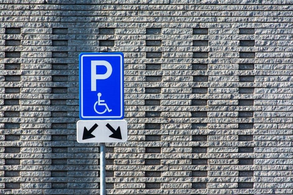
Permit Display Requirements
When parking in a designated disability parking bay, the Victorian Accessible Parking Permit must be clearly displayed. The permit, whether a digital PDF on a smartphone or a printed copy, needs to be visible from the vehicle’s dashboard. Ensure it’s positioned so that all details – permit number, expiry date, and holder’s name – are readily readable by enforcement officers.
If displaying a digital permit, the screen brightness must be sufficient for clear visibility, even in direct sunlight. The entire permit must be visible; cropped screenshots are not acceptable. For printed permits, avoid placing them behind tinted windows or in locations obstructed by other items. Proper display confirms your eligibility and prevents potential fines or towing.
Renewal Process for Existing Permits
Renewing your Victorian Disability Parking Permit is now primarily conducted online through the Accessible Parking Permits website. The streamlined process aims for efficiency and reduced administrative burden. However, renewal requirements differ based on the disability classification.

Permits issued for permanent disabilities benefit from automatic renewal, eliminating the need for periodic reassessments. This reflects the enduring nature of the condition. Conversely, permits granted for temporary disabilities necessitate reassessment to confirm continued eligibility. Applicants will receive notifications prompting them to re-apply and provide updated medical documentation. Failure to renew before expiry may result in the loss of parking privileges.
Automatic Renewal for Permanent Disabilities
Victorian Disability Parking Permits issued under a permanent disability classification now enjoy an automatic renewal process. This significant improvement, a key feature of the updated Accessible Parking Permit Scheme (APP), removes the administrative burden of repeated applications and medical reassessments for individuals with stable, long-term conditions.
This streamlined approach acknowledges the enduring nature of permanent disabilities, reducing unnecessary paperwork and associated costs. While automatic, permit holders are still responsible for ensuring their details remain current with the relevant authorities; The introduction of this permanent classification simplifies the renewal process, freeing up resources and focusing attention on those requiring periodic reassessment. It’s a positive step towards a more user-friendly system.
Reassessment Requirements for Temporary Disabilities
Individuals holding a Disability Parking Permit based on a temporary disability classification in Victoria will continue to require periodic reassessments. This is because temporary conditions, by their nature, are subject to change, necessitating verification of ongoing eligibility for the permit. The frequency of these reassessments is determined by a medical professional assessing the applicant’s condition during the initial application process.
These regular reviews ensure the permit is utilized appropriately and by those with a genuine, current need. Applicants must provide updated medical evidence demonstrating their continuing disability to support their renewal application. Failure to submit the required documentation may result in permit cancellation. The reassessment process is a vital component of maintaining the integrity of the scheme.
Misuse of Permits and Penalties
The Victorian Accessible Parking Permit Scheme (APP) strictly prohibits the misuse of disability parking permits. This includes using a permit belonging to someone else, displaying a fraudulent or altered permit, or parking in a disability bay without a valid permit displayed. Such actions demonstrate a blatant disregard for those genuinely reliant on accessible parking.
Penalties for misuse are significant and can include substantial fines, vehicle impoundment, and even criminal prosecution. Bayside City Council highlights that the streamlined APP Online Service aims to reduce misuse, freeing up bays for legitimate permit holders. Councils actively enforce parking regulations, and reports of misuse are taken seriously. Protecting access for those with disabilities is paramount, and penalties serve as a deterrent against unlawful behavior.
Reporting Misuse of Disability Parking Bays
If you witness the misuse of a disability parking bay in Victoria, reporting it is crucial to ensure accessibility for those who legitimately require it. While a centralized reporting system isn’t explicitly detailed, Latrobe City Council advises contacting your local council directly to report instances of permit misuse. This can typically be done through their website or customer service channels.
When reporting, provide as much detail as possible, including the vehicle registration number, the location of the bay, the date and time of the incident, and a description of the permit (if visible). Bayside City Council’s emphasis on reducing misuse through the APP Online Service underscores the importance of community vigilance. Prompt reporting helps councils enforce regulations and maintain the integrity of the scheme, ensuring bays remain available for eligible individuals.
Dispute Resolution Process
If your application for a Disability Parking Permit in Victoria is denied, or you disagree with a decision regarding your permit, a dispute resolution process is available. Latrobe City Council highlights the availability of information regarding dispute resolution, though specific details aren’t extensively outlined in readily available resources.
Generally, the first step involves contacting the council that processed your application to understand the reasons for the decision. You may be able to submit additional information or clarification to support your case. If you remain unsatisfied, further avenues for appeal may exist, potentially involving a review by a higher authority within the Victorian government. It’s advisable to document all communication and gather supporting medical evidence to strengthen your position throughout the process.
Vehicles Ineligible for Parking Permits
Certain vehicle types are specifically excluded from eligibility for a Disability Parking Permit within the Victorian Accessible Parking Permit Scheme (APP). Greater Dandenong Council clearly states that buses – defined as vehicles seating more than twelve people, including the driver – are ineligible. This restriction applies regardless of whether the bus is privately or commercially owned.
Furthermore, commercial passenger vehicles (CPVs), such as taxis, rideshare vehicles, and limousine services, are also explicitly excluded. These vehicles are used for transporting passengers for hire or reward and do not qualify for a permit, even if a driver or passenger holds a valid disability. This ensures that disability parking bays remain available for individuals with disabilities using privately owned vehicles for personal transport.
Buses and Commercial Passenger Vehicles
The Victorian Accessible Parking Permit Scheme (APP) maintains specific exclusions regarding buses and commercial passenger vehicles (CPVs). Buses, defined as any vehicle designed to carry over twelve individuals, including the driver, are categorically ineligible for a disability parking permit. This policy prevents large vehicles from occupying spaces intended for individuals with mobility impairments.
Similarly, CPVs – encompassing taxis, rideshare services, and limousine services – are also barred from obtaining permits. These vehicles operate for commercial purposes, transporting passengers for a fee, and are therefore not considered for the scheme’s benefits. This ensures equitable access for individuals relying on personal vehicles due to disability, preventing commercial operations from utilizing designated parking.
The Role of Local Councils in the APP
Victorian local councils play a crucial administrative role within the Accessible Parking Permit Scheme (APP), despite the introduction of a more streamlined, centralized online application process. Currently, all 79 Victorian councils continue to manage the scheme at the local level, handling aspects of permit administration and enforcement.
Councils are responsible for monitoring disability parking bays within their municipalities, addressing reports of misuse, and enforcing parking regulations. The shift towards the APP Online Service aims to reduce permit misuse, freeing up bays for those genuinely needing them, but councils remain vital for on-the-ground management. They also provide assistance to applicants who require paper forms or face difficulties with the online system.

Resources and Further Information
For comprehensive details regarding the Accessible Parking Permit Scheme (APP) in Victoria, the primary resource is the Victorian Government’s dedicated Accessible Parking Permits website. This platform facilitates online applications, renewals, and provides detailed eligibility criteria.
Individual local councils, such as Greater Dandenong, Bayside, and Cardinia Shire, also offer specific guidance and support related to the APP within their respective municipalities. Contacting your local council’s customer service center is recommended if you require a paper application form or have specific inquiries. Latrobe City Council provides helpful FAQs and information on dispute resolution processes. Remember the first World report on disability was produced in December 2011.