Categories
Manuals

motorola xpr 3500e user manual

Welcome to the Motorola XPR 3500e User Manual, your comprehensive guide to understanding and utilizing the advanced features of this MOTOTRBO digital radio series effectively.

1.1 Overview of the XPR 3500e Series

The Motorola XPR 3500e is a high-performance, digital two-way radio designed for critical communications. Part of the MOTOTRBO series, it offers enhanced features like WiFi connectivity for improved fleet management and safety applications such as Emergency Transmission, Lone Worker, and Man Down. Built for durability, the XPR 3500e supports VHF and UHF frequencies, ensuring reliable communication across various environments. It is compatible with Motorola and third-party accessories, making it a versatile solution for professional and industrial use.

1.2 Importance of the User Manual

The Motorola XPR 3500e User Manual is essential for maximizing the device’s capabilities and ensuring safe, effective operation. It provides detailed instructions for setup, configuration, and troubleshooting, helping users navigate advanced features like WiFi connectivity and safety applications. The manual also outlines compliance with regulatory standards and warranty terms, protecting both the user and the device. By following the guidelines, users can maintain peak performance, resolve common issues, and utilize all functionalities efficiently, making it an indispensable resource for professionals relying on this MOTOTRBO radio.

Key Features of the Motorola XPR 3500e

The Motorola XPR 3500e features advanced MOTOTRBO technology, including WiFi for improved fleet management, enhanced safety applications like Lone Worker, and a user-friendly design with customizable keypad and display options.

2.1 Technical Specifications

The Motorola XPR 3500e operates on VHF and UHF frequency bands, offering a maximum power output of 5W. It supports digital DMR standards and features WiFi connectivity for enhanced fleet management. The radio includes a high-resolution display and a limited keypad for user interaction. It is compatible with Bluetooth devices and supports advanced audio features like Trill Enhancement. The XPR 3500e is part of the MOTOTRBO series, designed for reliable communication in various environments. It complies with FCC Part 15 regulations and is built to withstand rigorous use, ensuring durability and performance.

2.2 User Interface and Controls

The Motorola XPR 3500e features an intuitive user interface designed for ease of operation. The high-resolution LCD display provides clear visibility of settings and status updates. The radio includes a limited keypad for direct channel selection and navigation buttons for scrolling through menus. Customizable buttons allow users to assign frequently used features for quick access. The interface supports user-selectable audio profiles and Trill Enhancement for improved sound quality. Designed for efficiency, the controls enable seamless navigation and operation, making it user-friendly for both novice and experienced users;

2.3 Enhanced Features (WiFi, Vibrate, etc.)

The Motorola XPR 3500e includes advanced features such as WiFi connectivity, enabling seamless fleet management and software updates. The vibrate function ensures discreet notifications, ideal for quiet environments. Enhanced audio capabilities like Trill Enhancement improve communication clarity. The radio also supports Bluetooth connectivity for pairing with compatible devices. These features, combined with a robust design, make the XPR 3500e a versatile and efficient communication tool, catering to diverse operational needs while maintaining reliability and user satisfaction in various professional settings.

Safety Features of the XPR 3500e

The XPR 3500e includes state-of-the-art safety features like emergency transmission, Lone Worker, and Man Down applications, ensuring user monitoring and immediate response capabilities in critical situations.

3.1 Emergency Transmission Features

The Motorola XPR 3500e is equipped with advanced emergency transmission features, ensuring rapid response in critical situations. Users can send emergency alerts with a single button press, prioritizing their transmissions over other communications. The radio also supports high-priority signaling, ensuring messages are delivered instantly. Additionally, the system can be programmed to monitor for inactive radios, triggering an alert if no movement or communication is detected within a set time frame. These features enhance workplace safety and provide peace of mind for teams operating in challenging environments. The emergency functionality integrates seamlessly with the radio’s software, allowing for real-time monitoring and swift action.

3.2 Lone Worker and Man Down Applications

The Motorola XPR 3500e supports Lone Worker and Man Down applications, enhancing safety for individuals working alone or in hazardous environments. The Lone Worker feature monitors user activity, sending alerts if no movement or communication occurs within a set time frame. The Man Down application uses a tilt sensor to detect if the radio is in a horizontal position for an extended period, triggering an emergency signal. These features ensure quick response in critical situations, providing an additional layer of protection and peace of mind for workers in isolated or high-risk conditions;

Installation and Setup

The Motorola XPR 3500e installation involves physical setup and software configuration. Follow guidelines for easy deployment and customize settings to meet operational needs effectively.

4.1 Physical Installation Guidelines

Ensure proper installation of the Motorola XPR 3500e by following physical setup guidelines. Mount the radio securely, connect antennas correctly, and power it using approved sources. Verify all cables are tightly secured to avoid signal loss. Position the device in a well-ventilated area to prevent overheating. Use Motorola-recommended accessories to maintain optimal performance. Always refer to the manual for specific installation diagrams and safety precautions. Proper physical installation ensures reliable operation and longevity of the device. Follow all safety measures to avoid damage or operational issues. Adhere strictly to Motorola’s installation recommendations for best results.

4.2 Software Setup and Configuration

Configure the Motorola XPR 3500e by updating its firmware to the latest version using Motorola-approved software tools. Activate licenses for advanced features like WiFi and custom profiles. Follow the user manual for step-by-step guidance on programming channels, voice annunciation, and security settings. Ensure Bluetooth pairing is enabled for compatible devices. Use Motorola’s CPS (Customer Programming Software) for seamless customization. Always back up settings before making changes. Proper software configuration ensures optimal performance and feature accessibility. Refer to the manual for troubleshooting tips and compliance with regulatory standards. Adhere to Motorola’s guidelines for a smooth setup process.

Operating the Motorola XPR 3500e

The Motorola XPR 3500e offers an intuitive interface for seamless communication. Access emergency features, navigate channels, and customize audio settings for efficient daily operations.

5.1 Basic Operations and Controls

The Motorola XPR 3500e operates with a user-friendly interface. Power on/off by pressing and holding the Power button. Adjust volume using the up/down keys. Select channels or talkgroups via the keypad or programmable buttons. Initiate voice communication by pressing the Push-to-Talk (PTT) button. Access menus by pressing the Menu button and navigate using the navigation keys. The emergency button triggers urgent transmissions. Use the limited keypad to input channel numbers or settings. LED indicators provide status updates, such as power, battery life, and transmission activity, ensuring efficient communication management.

5.2 Advanced Features and Customization

The Motorola XPR 3500e offers advanced features for enhanced communication. Enable Bluetooth connectivity for pairing with compatible devices. Use programmable buttons to assign custom functions, such as quick access to favorite channels or emergency alerts. Customize audio settings, including noise cancellation and voice enhancement, for clearer transmissions. The vibrate feature ensures discreet notifications. Users can also program the radio using Motorola’s software to tailor settings to specific needs. Additionally, the XPR 3500e supports WiFi connectivity for remote fleet management, enabling seamless updates and monitoring. These features allow for a personalized and efficient communication experience.

Maintenance and Troubleshooting

Regularly clean the radio and accessories to ensure optimal performance. Update software to access new features and improvements. Refer to the user manual for troubleshooting common issues like connectivity or audio problems. Always use authorized service centers for repairs to avoid warranty voidance.

6.1 Routine Maintenance Tips

Regularly inspect and clean the Motorola XPR 3500e to remove dirt or debris, ensuring proper functionality. Use a soft cloth and avoid harsh chemicals to prevent damage. Check the battery contacts periodically and clean them if necessary to maintain reliable power connections. Update the radio’s software to the latest version for optimal performance and security. Store the device in a cool, dry place to prevent overheating and moisture damage. Avoid exposing the radio to extreme temperatures or physical stress; For more detailed maintenance instructions, refer to the official user manual. Regular maintenance prolongs the device’s lifespan and ensures uninterrupted communication.

6.2 Common Issues and Solutions

Common issues with the Motorola XPR 3500e include connectivity problems, battery life concerns, and audio interference. For connectivity issues, reset the device or check network settings. Battery life can be extended by calibrating the battery or replacing it if necessary. Audio problems may require cleaning the speaker or adjusting volume settings. Software glitches can often be resolved by updating to the latest firmware version. Refer to the user manual for detailed troubleshooting steps and solutions to ensure optimal performance and resolve issues promptly. Regular updates and maintenance can prevent many of these problems.

Accessories and Compatibility

Approved Motorola accessories ensure optimal performance, while third-party options may be compatible. Use genuine headsets, chargers, and batteries for reliability. Non-approved items may affect functionality.

7.1 Approved Motorola Accessories

Motorola offers a wide range of approved accessories specifically designed for the XPR 3500e, ensuring optimal performance and compatibility. These include high-quality headsets, chargers, batteries, and speakers. Accessories like the Motorola PMMN4027 Remote Speaker Microphone and PMLN7189 Tactical Charging Cable enhance functionality. Approved devices are rigorously tested to meet Motorola’s standards, guaranteeing reliability and durability. Using genuine Motorola accessories ensures seamless integration with your radio, maintaining peak performance and user satisfaction. They are designed to withstand tough environments, making them ideal for professional use.

7.2 Third-Party Accessory Compatibility

The XPR 3500e supports select third-party accessories, provided they meet Motorola’s compatibility standards. Users can explore options like headsets, chargers, and carrying solutions from trusted manufacturers. However, it’s crucial to verify that these accessories comply with Motorola’s specifications to ensure optimal performance. Using non-approved devices may lead to functionality issues or void the warranty. Always consult the user manual or contact Motorola support for a list of verified third-party accessories to maintain your radio’s reliability and performance.

Licensing and Compliance

Ensure compliance with regulatory requirements and obtain necessary licenses for operation. Motorola products comply with FCC standards, and proper licensing is mandatory for certain features. Always follow local regulations.

8.1 Licensing Requirements

Licensing is essential for certain features of the Motorola XPR 3500e. Ensure you obtain necessary licenses to operate advanced functionalities, such as WiFi and fleet management tools. Compliance with local regulations is mandatory, and licenses must be acquired to avoid operational restrictions. Refer to the user manual for detailed instructions on licensing procedures and ensure all legal requirements are met before activating specific features. Failure to comply may result in operational limitations or legal consequences. Contact Motorola support for assistance with licensing inquiries.

8.2 Regulatory Compliance Information

The Motorola XPR 3500e is designed to meet regulatory standards worldwide, ensuring safe and legal operation. It complies with FCC Part 15 and other international regulations, minimizing radio frequency exposure. Proper installation and use, as outlined in the manual, are essential to maintain compliance. Unauthorized modifications may void regulatory certifications and operational authority. Always adhere to local laws and Motorola’s guidelines for environmental and safety standards. This ensures optimal performance while fulfilling legal requirements. Compliance is crucial for both user safety and device functionality.

Comparison with Other Motorola Models

The XPR 3500e stands out with enhanced features like WiFi and vibrate mode, offering superior fleet management compared to earlier models such as the XPR 3300e.

9.1 XPR 3500e vs. XPR 3300e

The XPR 3500e offers enhanced features compared to the XPR 3300e, including WiFi connectivity for improved fleet management and a vibrate mode for discreet notifications. While both models share a similar design and core functionalities, the XPR 3500e introduces advanced software capabilities and better customization options. The addition of WiFi in the XPR 3500e enables over-the-air programming and remote updates, making it more versatile for modern communication needs. These upgrades make the XPR 3500e a more robust choice for users requiring advanced connectivity and management features.

9.2 XPR 3500e vs. Other MOTOTRBO Models

The XPR 3500e stands out among other MOTOTRBO models with its integrated WiFi and enhanced user interface. Unlike the XPR 3000 series, it offers advanced customization options and improved audio quality. Compared to higher-tier models like the XPR 7000e, the XPR 3500e provides a balance of features and affordability, making it ideal for businesses seeking robust communication without unnecessary complexity. Its unique blend of performance and cost-effectiveness positions it as a versatile option in the MOTOTRBO lineup, catering to diverse operational needs across industries.

Warranty and Support

The Motorola XPR 3500e is backed by a limited warranty covering manufacturing defects for a specified period. Dedicated customer support and online resources ensure optimal assistance.

10.1 Warranty Information

The Motorola XPR 3500e is covered by a limited warranty that protects against manufacturing defects for a specified period from the date of purchase. This warranty ensures that any defective components will be repaired or replaced free of charge, provided the product has been used in accordance with the guidelines outlined in the user manual. The warranty does not cover damage resulting from misuse, normal wear and tear, or unauthorized modifications. For full details, including the warranty period and terms, refer to the official Motorola documentation or contact their support team. Registration of the product may be required to activate warranty benefits.

10.2 Customer Support and Resources

Motorola provides comprehensive customer support and resources to ensure optimal use of the XPR 3500e. Users can access the official Motorola website for detailed product guides, software updates, and troubleshooting tips. Additionally, the MOTOTRBO series offers dedicated customer service via phone or email for technical assistance. The XPR 3500e user manual and specification sheets are available in PDF format for easy reference. Motorola also offers training materials and online forums to help users maximize their radio’s capabilities. For further assistance, authorized Motorola dealers provide localized support and maintenance services.

Frequently Asked Questions (FAQs)

Discover answers to common queries about the Motorola XPR 3500e, such as software updates, emergency features, and customization options, to enhance your user experience effectively.

11.1 Common User Queries

Users often ask about software updates, emergency features, and customization options for the Motorola XPR 3500e. Common questions include how to enable WiFi, troubleshoot connectivity issues, and use Lone Worker applications. Many inquire about compatibility with third-party accessories and how to access the user manual. Others seek clarity on licensing requirements and warranty details. Additionally, users frequently ask about the differences between the XPR 3500e and other MOTOTRBO models, as well as how to perform routine maintenance to ensure optimal performance. These queries highlight the practical aspects of using the device effectively.

11.2 Troubleshooting FAQs

Common troubleshooting queries for the Motorola XPR 3500e include resolving power issues, connectivity problems, and emergency feature activation. Users often ask how to reset the device, fix failed software updates, and address “No Service” errors. Others seek solutions for distorted audio, keypad lockouts, and GPS functionality issues. Additionally, FAQs cover how to clear error codes, recover from firmware corruption, and restore factory settings. These troubleshooting tips help users quickly resolve common challenges and ensure uninterrupted communication.

The Motorola XPR 3500e user manual provides a detailed guide to maximizing the potential of this advanced MOTOTRBO digital radio. By following the outlined instructions, users can ensure optimal performance, safety, and reliability. The manual emphasizes ease of use, enhanced features, and troubleshooting solutions to address common challenges. With its robust design and cutting-edge technology, the XPR 3500e is a trusted communication tool for professionals. Regular updates and Motorola’s commitment to innovation ensure users stay connected and informed. This manual serves as a comprehensive resource for unlocking the full capabilities of the XPR 3500e series.

Categories
Manuals

liftmaster la500 manual

The LiftMaster LA500 Manual is a comprehensive guide for installing, operating, and maintaining the LA500 gate operator. It covers residential and light commercial applications, offering detailed instructions for proper setup and troubleshooting. The manual is available in multiple languages, ensuring accessibility for a wide range of users. It includes essential information on safety, technical specifications, and warranty details to ensure optimal performance and longevity of the device.

1.1 Overview of the LiftMaster LA500

The LiftMaster LA500 is a residential and light commercial swing gate operator designed for single-arm applications. It features a 24V DC actuator, ensuring smooth and reliable operation for gates weighing up to 800 pounds. The operator is compatible with a variety of gate types, including wood, vinyl, and metal. Its compact design and quiet operation make it an ideal choice for homeowners and businesses seeking a durable and efficient gate automation solution. The LA500 is also known for its advanced security features and customizable settings, catering to diverse user needs.

1.2 Importance of the Manual for Users

The LiftMaster LA500 Manual is essential for users to understand proper installation, operation, and maintenance of the gate operator. It provides critical safety guidelines, troubleshooting tips, and customization options, ensuring optimal functionality. The manual also outlines warranty details and technical specifications, helping users make informed decisions. Available in multiple languages and formats, it caters to diverse needs, making it an indispensable resource for both residential and light commercial applications. By following the manual, users can maximize the device’s performance and longevity while ensuring safe and efficient operation.

1.3 Key Features of the LiftMaster LA500

The LiftMaster LA500 is a vehicular swing gate operator designed for residential and light commercial use. It features a single arm package with a 24 VDC actuator arm, suitable for single swing gate applications. Key highlights include a robust design, compatibility with various gate sizes, and energy-efficient operation. The LA500 also offers customizable settings, ensuring adaptability to user preferences. Its advanced engineering ensures smooth and quiet performance, making it a reliable choice for gate automation. These features make the LA500 an ideal solution for homeowners and businesses seeking durable and efficient gate operation.

Downloading and Accessing the Manual

The LiftMaster LA500 Manual is available online in PDF format, accessible in multiple languages like English, French, and Spanish. Users can download it directly from authorized sources.

2.1 Where to Find the LiftMaster LA500 Manual Online

The LiftMaster LA500 Manual is readily available online through various channels. The primary source is the official LiftMaster website, where users can download it directly. Additionally, it can be found on trusted third-party websites specializing in user manuals. The manual is provided in multiple languages, including English, French, and Spanish, catering to a diverse audience. Users can search for “LiftMaster LA500 Manual PDF” to access the document quickly. Ensure to download from verified sources to avoid unauthorized modifications or outdated versions.

2.2 How to Download the Manual in PDF Format

To download the LiftMaster LA500 Manual in PDF format, visit the official LiftMaster website or authorized distributors. Search for the LA500 model, select your preferred language, and click the download link. Ensure you choose the correct version for your device. The manual is also available on platforms like ManualsLib or Scribd. Once downloaded, save the PDF for easy access. Verify the file integrity and ensure it matches your LA500 or LA500-S model to avoid confusion. A stable internet connection is recommended for a smooth download process.

2.3 Languages Available for the Manual

The LiftMaster LA500 Manual is available in multiple languages, including English, French, and Spanish, catering to a diverse user base. This ensures that users from different regions can easily understand and follow the instructions. The manual can be downloaded in these languages from the official LiftMaster website or authorized support pages. This accessibility feature enhances user experience and ensures proper installation and operation of the LA500 gate operator. Language options are clearly indicated on the download page, making it easy for users to select their preferred version.

Installation Instructions

The LiftMaster LA500 Manual provides a comprehensive guide for the installation process, covering residential and light commercial applications with detailed steps for proper setup and troubleshooting.

3.1 Pre-Installation Requirements

Before installing the LiftMaster LA500, ensure the gate is structurally sound and within weight and size limits specified in the manual. Verify the power supply meets the required voltage and ensure all necessary tools and materials are available. Check for any obstructions or hazards in the installation area. Review safety guidelines to prevent accidents during the process. Ensure the gate is balanced and properly aligned before proceeding. Familiarize yourself with the manual’s instructions to avoid mistakes. Proper preparation is crucial for a smooth and successful installation.

3.2 Step-by-Step Installation Guide

The installation begins with assembling the gate operator components, ensuring all hardware is included. Mount the control box securely, then attach the actuator arm to the gate and operator. Connect the motor and wiring according to the manual’s diagram. Test the limit switches and align the arm for smooth operation. Finally, power the system and perform a safety check to ensure proper function. Refer to the manual for specific torque settings and wiring instructions to avoid errors.

3.3 Tools and Materials Needed

To successfully install the LiftMaster LA500, you’ll need specific tools and materials. Essential tools include a wrench, drill, screwdriver, level, and pliers. Materials required are screws, brackets, and cables. Safety gear like gloves and goggles is recommended. Ensure all components from the package are included. Refer to the manual for a detailed list to avoid missing any items. Proper preparation ensures a smooth installation process and optimal performance of the gate operator.

Features and Benefits

The LiftMaster LA500 offers advanced security features, customizable settings, and compatibility with various gate types for residential and light commercial use, ensuring reliable performance.

4.1 Residential and Light Commercial Use

The LiftMaster LA500 is designed for both residential and light commercial applications, offering versatility for various gate operation needs. It supports gates weighing up to 800 pounds and measuring up to 16 feet wide, making it suitable for larger properties. The manual provides specific guidelines for installation and operation in both settings, ensuring safe and efficient use. Whether for home security or commercial access control, the LA500 delivers reliable performance. Its durable construction and advanced features cater to the demands of both environments, making it a practical choice for homeowners and businesses alike.

4.2 Advanced Security Features

The LiftMaster LA500 boasts advanced security features designed to protect your property and ensure safe operation. It includes encrypted signal technology to prevent unauthorized access and tampering. The system is equipped with monitoring capabilities, allowing real-time tracking of gate status. Additionally, the manual highlights features like automatic locking and alarm notifications for enhanced security. These features not only deter intruders but also provide peace of mind for homeowners and businesses. The LA500 prioritizes user safety while maintaining reliability and efficiency, making it a top choice for secure gate automation solutions.

4.3 Customizable Settings and Options

The LiftMaster LA500 offers a range of customizable settings to tailor operation to user preferences. Adjustments can be made to sensitivity, timer settings, and gate speed, ensuring smooth and efficient performance. Users can also program specific opening and closing angles, which is particularly useful for gates of varying sizes. Additionally, the system allows for customizing access controls and security features, enhancing convenience and safety. These adaptable options make the LA500 ideal for both residential and light commercial applications, providing flexibility to meet diverse user needs and gate configurations.

Technical Specifications

The LiftMaster LA500 requires a 24V DC power supply, supporting gates up to 800 pounds and 16 feet wide. The primary actuator arm is designed for single-swing applications, with optional secondary arms for larger gates.

5.1 Power Requirements and Voltage

The LiftMaster LA500 requires a 24V DC power supply, ensuring smooth and efficient operation for residential and light commercial gates. It is compatible with a wide range of gate sizes and weights, making it versatile for various applications. The manual specifies that the operator must be connected to a dedicated 120V AC, 60Hz power source for proper functionality. Dual-voltage models may also be available, but the LA500 primarily operates on 24V DC. This low voltage enhances safety and reduces energy consumption, while the battery backup feature ensures operation during power outages.

5.2 Gate Weight and Size Limitations

The LiftMaster LA500 is designed to handle gates weighing up to 500 pounds and measuring up to 16 feet in width for single gates, or 8 feet per leaf for dual gates. Exceeding these limits may result in reduced performance or motor strain. Proper installation and alignment are crucial to ensure safe and efficient operation. Adhering to these specifications guarantees optimal functionality and longevity of the operator. Always verify gate dimensions and weight before installation to avoid potential issues.

5.3 Motor and Actuator Details

The LiftMaster LA500 features a powerful 24 VDC actuator arm designed for single swing gate applications. The motor is engineered for durability and smooth operation, ensuring reliable performance in various conditions. The actuator’s advanced design minimizes noise and maximizes efficiency, making it suitable for both residential and light commercial use. The manual provides detailed specifications, including torque ratings and operational speeds, to help users understand the motor’s capabilities. This section also highlights how the actuator integrates with the gate operator system to ensure seamless functionality and longevity of the equipment.

Maintenance and Care

Regular maintenance ensures optimal performance. Lubricate moving parts, clean the gate and operator, and check the battery. Refer to the manual for specific intervals and guidelines.

6.1 Regular Maintenance Schedule

Regular maintenance is crucial for ensuring the longevity and smooth operation of your LiftMaster LA500. A recommended schedule includes monthly checks of the battery, screws, and lubrication points. Every three months, inspect the chain or belt for wear and tighten any loose connections. Annually, perform a full system inspection, checking for worn parts and ensuring proper alignment. Additionally, clean the control box and sensors to prevent debris buildup. Following this schedule helps prevent unexpected failures and ensures optimal performance of your gate operator.

6.2 Lubrication and Cleaning Tips

Regular lubrication ensures smooth operation of the LiftMaster LA500 gate operator. Apply silicone-based lubricant to moving parts like hinges and chains every 6 months. Avoid grease, as it attracts dust. For cleaning, use a soft cloth and mild detergent to wipe down the actuator and control box. Never use harsh chemicals or high-pressure washes, as they may damage components. Cleaning ensures optimal performance and prevents corrosion. Lubrication and maintenance routines are detailed in the manual to prolong the lifespan of your gate operator and maintain reliability.

6.3 Battery Care and Replacement

Proper battery care is essential for ensuring the LiftMaster LA500 operates reliably. Regularly inspect the battery terminals for corrosion and clean them if necessary. Avoid deep discharges by recharging the battery when the indicator shows low power. Store batteries in a cool, dry place during off-seasons to prevent degradation. For replacement, use compatible batteries recommended in the manual. Ensure the system is powered off before swapping batteries to avoid electrical issues. Always follow safety precautions, such as wearing gloves and working in a well-ventilated area. Refer to the manual for specific replacement guidelines to maintain warranty validity.

Troubleshooting Common Issues

The LiftMaster LA500 Manual provides guidance for resolving common issues, such as error codes and operational problems, ensuring smooth functionality and addressing potential malfunctions effectively.

7.1 Identifying Common Problems

Common issues with the LiftMaster LA500 often relate to gate alignment, power supply, or sensor malfunctions. Users may experience inconsistent operation, such as the gate not closing fully or opening unexpectedly. Error codes displayed on the control panel can help identify specific problems, such as obstruction detection or battery issues. The manual provides a troubleshooting section with symptoms and solutions, guiding users to check components like photo eyes, limits, and wiring; Regular maintenance, as outlined in the manual, can prevent many of these issues. Addressing problems early ensures smooth operation and extends the system’s lifespan.

7.2 Error Codes and Solutions

The LiftMaster LA500 Manual provides a detailed list of error codes and their corresponding solutions to help users diagnose and resolve issues efficiently. Common error codes like E1 and E2 indicate specific problems, such as obstruction detection or limit setting issues. The manual guides users through troubleshooting steps, including resetting the system or adjusting the gate’s limit settings. Additionally, it offers solutions for addressing communication errors between components, ensuring smooth operation. By following the manual’s instructions, users can quickly identify and fix problems, minimizing downtime and ensuring the gate operator functions optimally. Regular updates and FAQs are also available for further assistance.

7.3 Resetting the System

Resetting the LiftMaster LA500 system is a straightforward process designed to restore default settings and resolve operational glitches. Users can perform a soft reset by disconnecting the power supply for 10 seconds and reconnecting it, which often resolves minor issues. For a factory reset, refer to the manual for specific instructions, as this may vary depending on the model. It is important to note that resetting will erase custom settings, so ensure these are documented before proceeding. Always consult the manual or contact support if unsure about the reset process to avoid potential system malfunctions.

Safety Precautions

Adhere to safety guidelines during installation and operation to prevent accidents. Ensure proper installation and regular maintenance to avoid mechanical hazards. Always use emergency stop features in case of malfunctions.

8.1 Safety Guidelines for Installation

Always disconnect power before starting installation to avoid electrical hazards. Wear protective gear, including gloves and safety glasses, to prevent injury. Ensure the area is clear of obstacles and bystanders. Follow the manual’s instructions precisely to avoid improper setup. Properly ground the device to prevent shock or malfunction. Never overload the gate operator beyond its weight and size limitations. Test the system after installation to ensure smooth operation. If unsure, consult a professional installer. Regular inspections and maintenance are crucial to maintain safety standards over time.

8.2 Operating Safety Tips

Always ensure the gate area is clear of people and objects before operation. Avoid unauthorized adjustments to the gate or operator. Keep children away from control buttons. Regularly inspect the gate and operator for wear or damage. Never manually operate the gate while the motor is running. Ensure the gate is properly aligned and balanced. Avoid overriding safety features. Keep the remote control out of reach of children. Test the gate’s reversing mechanism monthly. Ensure proper voltage supply to the operator. Follow all safety guidelines outlined in the LiftMaster LA500 Manual for optimal performance and user safety.

8.3 Emergency Stop and Safety Features

The LiftMaster LA500 Manual emphasizes the importance of emergency stop and safety features to prevent accidents. It outlines how to activate the emergency stop mechanism and lists safety sensors designed to detect obstacles. The manual also provides instructions for testing these features to ensure proper functionality. Additional safety measures include alarm systems and indicator lights that alert users to potential issues. By following the manual’s guidelines, users can configure these features to maximize safety for both residential and commercial applications, ensuring reliable operation and minimizing risks associated with gate movement.

Warranty and Support

The LiftMaster LA500 is backed by a comprehensive warranty, ensuring coverage for parts and labor. Dedicated customer support is available for troubleshooting and inquiries, with online resources and FAQs providing additional assistance.

9.1 Warranty Coverage and Terms

The LiftMaster LA500 Manual outlines a comprehensive warranty program designed to protect your investment. The warranty typically covers parts and labor for a specified period, ensuring defective components are repaired or replaced free of charge. Terms vary by region and model, with specific conditions for residential and light commercial use. Proper installation and maintenance, as detailed in the manual, are often required to maintain warranty validity. For exact terms and conditions, refer to the dedicated warranty section in the manual or contact LiftMaster customer support for clarification.

9.2 Customer Support Contact Information

For assistance with the LiftMaster LA500, customers can contact the dedicated support team. The official website provides a support page with contact details, including phone numbers and email options. Users can reach out to the customer service department for inquiries, troubleshooting, or warranty-related issues. Additionally, regional support numbers are available for specific countries, ensuring prompt assistance. Visit the LiftMaster website for the most accurate and up-to-date contact information to resolve any concerns efficiently.

  • Phone: 1-800-528-9151 (US only)
  • Email: Available through the official website
  • Website: [www.liftmaster.com](https://www.liftmaster.com)

Customer support is available to address installation, operation, or maintenance questions, ensuring a smooth experience with the LA500 operator.

9.3 Online Resources and FAQs

The LiftMaster LA500 Manual is supported by extensive online resources, including troubleshooting guides and FAQs. Users can access detailed instructions, video tutorials, and technical specifications on the official LiftMaster website. The FAQs section addresses common issues, such as installation difficulties, error codes, and maintenance tips. Additionally, online forums and customer support portals provide further assistance. These resources ensure users can resolve problems quickly and efficiently, enhancing their overall experience with the LA500 gate operator. They also empower users to make informed decisions about customization and maintenance.

Comparison with Other Models

The LiftMaster LA500 stands out for its versatility in residential and light commercial use. Compared to the LA500-S model, it offers enhanced features and durability, making it a preferred choice for heavier gates and demanding applications.

10.1 Differences from LA500-S Model

The LiftMaster LA500-S model differs from the standard LA500 by offering enhanced features tailored for specific applications; The LA500-S often includes additional security measures, such as advanced encryption for wireless communication, and may support heavier gate weights. It also features a more robust actuator design, making it suitable for larger or high-traffic gates. The LA500-S model may include optional add-ons like solar power compatibility or integrated battery backup, providing greater flexibility for users with unique needs. These upgrades make the LA500-S a preferred choice for users requiring advanced performance and durability compared to the standard LA500 model.

10.2 Comparison with Other LiftMaster Models

The LiftMaster LA500 stands out among other models in the lineup due to its unique blend of residential and light commercial functionality. Unlike heavier-duty models, the LA500 is designed for smaller gates, offering a more compact and energy-efficient solution. While models like the LA400 series focus on heavy-duty applications, the LA500 excels in versatility, with customizable settings and advanced security features. It also differs from the LA500-S model, which includes additional safety sensors. This makes the LA500 a preferred choice for homeowners seeking a reliable yet affordable gate operator without compromising on performance or safety.

10.3 Unique Selling Points of the LA500

The LiftMaster LA500 stands out for its versatility in both residential and light commercial applications, offering advanced security features and customizable settings. Its robust design ensures durability, while the comprehensive manual provides clear guidance for installation and maintenance. The availability of the manual in multiple languages enhances accessibility. With features like customizable settings and advanced security, the LA500 is a reliable choice for swing gate automation, catering to a wide range of user needs efficiently.

User Reviews and Feedback

Users praise the LiftMaster LA500 for its ease of installation and reliable performance. Many highlight its durability and smooth operation, while some note occasional connectivity issues. Overall, customer satisfaction is high.

11.1 Positive Aspects Highlighted by Users

Users consistently praise the LiftMaster LA500 for its ease of installation, durability, and reliability. Many highlight its smooth and quiet operation, making it ideal for residential use. The manual’s clarity and detailed instructions are often commended, ensuring even DIY installations go smoothly. Customers also appreciate the robust security features and customizable settings, which enhance convenience and safety. Positive feedback frequently mentions excellent customer support and the availability of online resources. Overall, users express high satisfaction with the product’s performance, longevity, and value for money, making it a top choice for swing gate automation.

11.2 Common Complaints and Concerns

Some users have reported issues with the LiftMaster LA500, including noise during operation and occasional connectivity problems with smart devices. A few customers found the programming process complex, while others noted that the battery life could be shorter than expected, especially in high-usage scenarios. Additionally, some users mentioned that the manual’s instructions, particularly for troubleshooting, could be more detailed. However, LiftMaster’s customer support has been praised for addressing these concerns promptly; Overall, while the LA500 is well-regarded, these feedback points highlight areas where improvements could enhance user satisfaction.

11.3 Overall Satisfaction Rating

The LiftMaster LA500 has received positive feedback, with users praising its reliability and performance. Many highlight its ease of use and robust security features, making it a top choice for residential and light commercial applications. Overall satisfaction ratings are high, with users appreciating its durability and quiet operation. The manual’s clarity and comprehensive troubleshooting section have also been commended. While some users note minor issues with installation complexity, the majority agree that the LA500 delivers excellent value and long-term reliability, solidifying its reputation as a trusted gate operator.

The LiftMaster LA500 Manual provides essential insights for optimal use, ensuring smooth installation, operation, and maintenance. It is a valuable resource for residential and light commercial applications, satisfying users with its comprehensive guidance and reliability.

12.1 Summary of Key Points

The LiftMaster LA500 Manual provides a comprehensive guide for installation, operation, and maintenance of the LA500 gate operator. It covers residential and light commercial applications, offering detailed instructions for setup and troubleshooting. Available in multiple languages, the manual ensures accessibility for diverse users. Key topics include safety precautions, technical specifications, and warranty details, ensuring optimal performance and longevity. The manual also highlights advanced security features, customizable settings, and essential maintenance schedules. With clear instructions and troubleshooting tips, it serves as an invaluable resource for users to maximize their device’s functionality and reliability.

12.2 Final Thoughts on the LiftMaster LA500

The LiftMaster LA500 stands out as a reliable and versatile gate operator, ideal for residential and light commercial use. Its robust design, advanced security features, and customizable settings make it a top choice for homeowners and businesses. The availability of a comprehensive manual in multiple languages ensures ease of use and maintenance. With its durable construction and user-friendly interface, the LA500 delivers long-term performance and satisfaction. For those seeking a blend of functionality, safety, and convenience, the LiftMaster LA500 is an excellent investment for secure and efficient gate operation.

12.3 Recommendations for Potential Buyers

Potential buyers considering the LiftMaster LA500 should evaluate their specific needs for residential or light commercial applications. Ensure the gate weight and size align with the operator’s limitations. Review the manual for installation requirements and safety guidelines to avoid complications. Comparing the LA500 with other models, such as the LA500-S, can help determine the best fit. Buyers should also check warranty terms and customer support options. Reading user reviews and feedback can provide insights into real-world performance and satisfaction. Finally, ensure compatibility with existing gate systems and consider future maintenance needs for long-term functionality.

Categories
Manuals

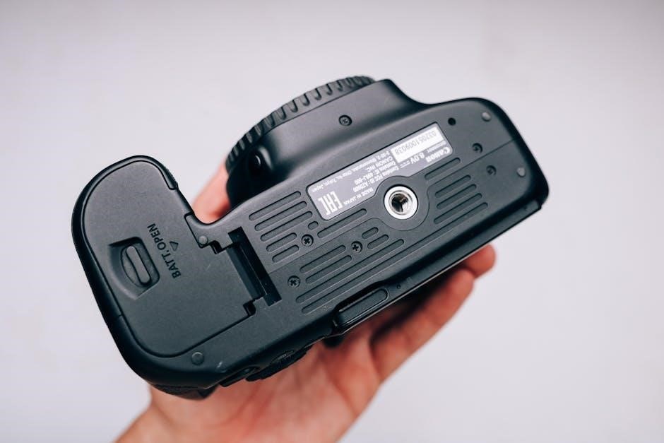
manual canon 80d

The Canon EOS 80D is a versatile DSLR camera designed for enthusiasts and semi-professionals, offering a 24.2MP APS-C sensor, Wi-Fi, NFC, and Full HD video recording. Its manual provides comprehensive guidance for optimal use.

1.1 Overview of the Canon EOS 80D

The Canon EOS 80D is a versatile DSLR camera designed for enthusiasts and semi-professionals, featuring a 24.2MP APS-C sensor. It supports Wi-Fi and NFC for seamless connectivity and offers Full HD video recording. The camera is known for its improved autofocus and enhanced image quality, making it ideal for both photography and videography. The manual provides detailed guidance to unlock its full potential and customize settings for optimal performance.

1.2 Importance of the Manual for Optimal Use

The Canon EOS 80D manual is essential for unlocking the camera’s full potential. It provides detailed instructions on advanced features, customization options, and troubleshooting tips. By studying the manual, users can master settings like autofocus, metering, and video recording. It also guides users on downloading additional software and firmware updates, ensuring optimal performance and empowering photographers to achieve professional-quality results.

Key Features of the Canon EOS 80D

The Canon EOS 80D features a 24.2MP APS-C sensor, delivering high-quality images, a 45-point autofocus system for precise subject tracking, and Full HD video recording for videography. It also includes built-in Wi-Fi and NFC for seamless connectivity and sharing.

2.1 Sensor and Image Quality

The Canon EOS 80D is equipped with a 24.2-megapixel APS-C CMOS sensor, ensuring high-resolution images with exceptional detail. It supports a wide ISO range of 100-16000, allowing for excellent low-light performance. The sensor’s advanced technology minimizes noise and captures vibrant colors, making it ideal for both still photography and video recording. This feature is extensively covered in the Canon EOS 80D manual.

2.2 Autofocus System

The Canon EOS 80D features a 45-point all-cross-type AF system, providing precise and fast autofocus performance. This advanced system is highly effective for tracking moving subjects and works seamlessly in various lighting conditions. The manual details how to customize AF settings, such as selecting AF points and using different AF modes like One-Shot AF and AI Servo AF for optimal results.

2.3 Video Capabilities

The Canon EOS 80D supports Full HD 1080p video recording at 60 fps, offering smooth and detailed footage. It features a built-in stereo microphone with manual audio level adjustment and a headphone jack for monitoring. The manual provides guidance on settings like frame rates, Movie Servo AF, and recording formats to enhance video production. This makes it ideal for content creators and videographers aiming for high-quality output.

2.4 Connectivity Options (Wi-Fi, NFC)

The Canon EOS 80D features built-in Wi-Fi and NFC, enabling wireless image transfer to devices and remote shooting via the Canon Camera Connect app. These features simplify sharing and control, making it ideal for modern photographers. The manual provides detailed instructions on setting up and using these connectivity options effectively, ensuring seamless integration with smartphones and other compatible devices.

Understanding the Canon EOS 80D Manual

The Canon EOS 80D manual is a comprehensive guide providing detailed instructions for camera operations, features, and troubleshooting. Available in PDF, it ensures optimal use of the camera.

3.1 Structure and Content of the Manual

The Canon EOS 80D manual is a comprehensive guide organized into sections covering camera setup, shooting modes, autofocus, metering, video settings, connectivity, troubleshooting, and maintenance. It includes detailed explanations of features, step-by-step instructions, and visual aids to help users master the camera. The manual is available in PDF format, ensuring easy access and readability. Its clear structure makes it a valuable resource for both beginners and advanced photographers.

3.2 Downloading the Manual (PDF Files)

The Canon EOS 80D manual can be downloaded as a PDF file from Canon’s official website at www.canon.com/icpd. The manual is free and available in multiple languages, offering detailed instructions for camera setup, features, and troubleshooting. Ensure you use Adobe Reader 6.0 or later to view the PDF file. This digital format provides easy access and portability for users.

3.3 Types of Manuals Available (Basic and Detailed)

The Canon EOS 80D offers two types of manuals: the Basic Instruction Manual, which provides essential operating instructions, and the Detailed Manual, available as a downloadable PDF file. The detailed manual covers advanced features, settings, and troubleshooting, ensuring users can maximize their camera’s potential. Both resources are accessible via the Canon website, catering to varying user needs and expertise levels.

Setting Up Your Canon EOS 80D

The Canon EOS 80D setup involves configuring date, time, language, and shooting settings. The manual guides initial configuration and customization options for optimal camera performance easily.

4.1 Initial Setup and Configuration

The Canon EOS 80D initial setup includes setting the date, time, and language via the menu; The manual guides configuring shooting parameters like image quality and white balance. Users can also enable features like Wi-Fi and NFC for wireless connectivity. Following these steps ensures the camera is ready for optimal performance and personalized use.

4.2 Customizing Camera Settings

The Canon EOS 80D allows users to customize settings to suit their preferences. The manual provides guidance on tailoring options like button assignments and menu configurations. Using the My Menu feature, frequently used settings can be accessed quickly. This personalization enhances shooting efficiency and ensures a more intuitive experience for photographers of all skill levels.

Shooting Modes and Settings

The Canon EOS 80D offers various shooting modes, including Manual, Aperture Priority, Shutter Priority, and Auto. The manual explains each mode in detail, helping users optimize their photography.

5.1 Explanation of Different Shooting Modes

The Canon EOS 80D manual details various shooting modes, including Manual (M), Aperture Priority (Av), Shutter Priority (Tv), Program (P), Auto, and Bulb. Each mode offers unique control over exposure settings, enabling photographers to capture images according to their creative vision. The manual provides clear guidance on optimizing these modes for different scenarios, ensuring users can make the most of the camera’s capabilities.

5.2 Adjusting Exposure and Metering

The Canon EOS 80D manual explains how to adjust exposure using metering modes like Evaluative, Center-Weighted, and Spot. Exposure compensation can be fine-tuned using the Quick Control dial, while AE Lock freezes exposure settings. These features allow precise control over lighting, ensuring balanced and professional results in various shooting conditions.

Autofocus and Metering

The Canon EOS 80D manual details its advanced 45-point AF system and metering modes, enabling precise focus and exposure control for capturing sharp, well-balanced images.

6.1 Using the Autofocus System Effectively

The Canon EOS 80D manual outlines techniques to maximize its 45-point AF system. Use the manual mode to select focus points, ensuring subjects are sharp. Adjust settings for moving subjects and utilize continuous AF for dynamic shots. Customizing AF preferences enhances performance for various photography scenarios, from portraits to wildlife.

6.2 Understanding Metering Modes

The Canon EOS 80D manual explains three metering modes: Evaluative, Center-Weighted, and Spot. Evaluative metering analyzes the entire scene for balanced exposure. Center-Weighted prioritizes the center, while Spot metering focuses on a specific area. Adjusting these modes via the Quick Control screen ensures accurate exposure control, tailored to your shooting conditions and creative vision.

Video Recording and Audio Settings

The Canon EOS 80D supports Full HD video recording with manual audio level adjustment via its built-in stereo microphone, ensuring high-quality sound and precise control.

7.1 Best Practices for Video Shooting

For optimal video recording with the Canon EOS 80D, use manual focus or continuous AF for smooth tracking. Shoot in MP4 format for smaller files and utilize the built-in stereo microphone with manual audio level adjustment for clear sound. Stabilize the camera using a tripod or IS lenses to minimize shake and ensure professional-grade footage.

7.2 Manual Audio Level Adjustment

The Canon EOS 80D allows manual audio level adjustment, enabling precise control over sound recording. This feature is particularly useful for reducing wind noise or balancing audio levels. When recording video, you can adjust the levels directly on the camera or use an external microphone for higher quality sound, ensuring clear and professional-grade audio capture.

Built-In Wi-Fi and Connectivity

The Canon EOS 80D features built-in Wi-Fi and NFC for seamless wireless connectivity, enabling easy image transfer to devices and remote camera control via the Canon Camera Connect app.

8.1 Transferring Images Wirelessly

The Canon EOS 80D allows users to transfer images wirelessly using built-in Wi-Fi and NFC. This feature enables seamless sharing to smartphones, tablets, and computers. The Canon Camera Connect app facilitates easy transfer and remote shooting. Additionally, images can be uploaded directly to cloud storage or social media platforms for instant accessibility and sharing. This enhances workflow efficiency for photographers on the go.

8.2 Connecting to Other Devices and Cameras

The Canon EOS 80D supports seamless connectivity with other devices and cameras via Wi-Fi and NFC. Users can transfer images between cameras or to external devices like smartphones, tablets, and printers using the Canon Camera Connect app. This feature also enables remote shooting and wireless backup, enhancing collaboration and workflow efficiency for photographers.

Accessories and Compatibility

The Canon EOS 80D is compatible with EF-S lenses, external flashes, and battery grips, enhancing its versatility for photography and videography.

9.1 Compatible Lenses and Accessories

The Canon EOS 80D supports a wide range of EF-S lenses, including the EF-S 18-135mm f/3.5-5.6 IS USM, and is compatible with external flashes, battery grips, and remote controllers. These accessories enhance functionality and adaptability for diverse photography needs.

9.2 Using External Microphones and Headphones

The Canon EOS 80D features a built-in stereo microphone with manual audio level adjustment and a headphone jack for real-time monitoring. External microphones can be connected for enhanced sound quality, while headphones allow precise audio monitoring. These features are ideal for professional video recording and ensure high-quality sound capture.

Tips for Getting the Best Results

Mastering manual mode and optimizing image quality are key to achieving professional results with the Canon EOS 80D. Experiment with settings and techniques to enhance your photography.

10.1 Mastering Manual Mode

To master manual mode on the Canon EOS 80D, start by understanding aperture, shutter speed, and ISO. Practice adjusting these settings to control depth of field, motion, and exposure. Use the camera’s built-in metering tools to guide your adjustments and experiment with different lighting conditions to refine your skills. Regular practice will enhance your creative control.

10.2 Optimizing Image Quality

To optimize image quality on the Canon EOS 80D, use RAW format for better editing flexibility. Select the highest resolution and apply Picture Styles for enhanced color and contrast. Adjust noise reduction settings for low-light shots and enable lens corrections for sharper images. Regularly clean the sensor to avoid dust spots and use high-quality lenses for superior sharpness.

Troubleshooting Common Issues

The Canon EOS 80D manual helps resolve errors and firmware issues. Regular updates ensure optimal performance, while the manual provides solutions for common problems like error messages.

11.1 Resolving Error Messages

The Canon EOS 80D manual provides detailed solutions for resolving error messages. Regular firmware updates and proper camera maintenance can prevent issues. Refer to the manual for troubleshooting steps and solutions to ensure optimal performance and address common problems effectively.

11.2 Updating Firmware and Software

The Canon EOS 80D manual outlines the process for updating firmware and software. Visit the official Canon website to download the latest versions. Follow the manual’s step-by-step instructions to ensure smooth updates, enhancing camera functionality and performance. Regular updates are crucial for maintaining optimal camera operation and accessing new features.

Advanced Features and Customization

The Canon EOS 80D offers advanced customization options, including My Menu for quick access and custom button assignments, enhancing user efficiency and personalization.

12.1 Using My Menu for Quick Access

The My Menu feature allows users to customize their workflow by adding frequently used settings for quick access. This streamlines operations, making it easier to adjust camera functions during shoots. By organizing essential options, photographers can save time and focus on capturing moments. The manual provides detailed steps to set up and personalize My Menu according to individual preferences.

12.2 Customizing Buttons and Functions

The Canon EOS 80D allows users to customize camera buttons and functions to suit their shooting style. Through the Custom Functions menu, photographers can assign specific tasks to buttons, ensuring quick access to preferred settings. This feature enhances efficiency, enabling seamless adjustments during photo or video sessions. The manual details how to tailor button assignments for personalized control.

Maintenance and Care

Regular cleaning of the sensor and lens ensures optimal image quality. Proper storage and transportation protect the camera from damage. Update firmware regularly for best performance.

13.1 Cleaning the Sensor and Lens

Regular cleaning of the sensor and lens is crucial for maintaining image quality. Use a hand blower to remove dust from the sensor, and a microfiber cloth for the lens. Avoid touching the sensor surface. For stubborn spots, use a cleaning solution with a soft cloth. Always refer to the manual for detailed cleaning instructions to ensure safety and effectiveness. Proper care extends the camera’s lifespan.

13.2 Storing and Transporting the Camera

Store the Canon EOS 80D in a cool, dry place, away from direct sunlight. Use a protective case or silica gel packets to prevent moisture damage. When transporting, ensure the camera is securely packed in a padded bag or hard case to avoid scratches and shocks. Always follow the manual’s guidelines for safe storage and transport to maintain the camera’s condition and functionality.

The Canon EOS 80D manual is essential for unlocking its full potential, offering detailed guidance for photographers to enhance their skills and capture stunning images effortlessly.

14.1 Summary of Key Takeaways

The Canon EOS 80D manual highlights its 24.2MP sensor, Dual Pixel AF, and 4K video capabilities. It emphasizes customization, Wi-Fi connectivity, and manual audio adjustments for enhanced creativity. Practical tips optimize image quality, while troubleshooting guides resolve common issues, ensuring users maximize their camera’s potential effectively.

14.2 Encouragement to Explore Further

With the Canon EOS 80D, explore advanced features like manual mode and custom settings for unique results. Experiment with different lenses and accessories to expand creative possibilities. Regularly update firmware and software for optimal performance, and refer to the manual for detailed guidance to unlock your full photographic potential.

Categories
Manuals

manual therapy for spinal stenosis therapist in overland park ks

Spinal stenosis is a common condition causing pain and mobility issues, often due to narrowing of the spinal canal. Manual therapy, offered by specialists in Overland Park, KS, provides effective treatment options.

What is Spinal Stenosis?

Spinal stenosis is a condition characterized by the narrowing of the spinal canal, which can compress nerves and lead to pain, numbness, and mobility issues. It often affects the neck or lower back and is common in older adults. This narrowing can result from aging, herniated discs, or other spinal abnormalities. If left untreated, it may cause neurogenic claudication or radicular pain. Manual therapy, offered by specialists in Overland Park, KS, is a proven approach to alleviate symptoms and improve quality of life for patients with this condition.

Symptoms and Diagnosis

Common symptoms of spinal stenosis include lower back pain, numbness, tingling, and weakness in the legs or arms. Patients may experience neurogenic claudication, limiting their ability to stand or walk for long periods. Diagnosis involves a physical exam, patient history review, and imaging tests like MRI or CT scans. Early detection is crucial for effective treatment. Therapists in Overland Park, KS, use specialized techniques to assess symptoms and develop personalized treatment plans, ensuring accurate diagnosis and proper care for optimal recovery.

Importance of Early Treatment

Early treatment of spinal stenosis is vital to prevent progression and reduce pain. Manual therapy, when applied promptly, can improve mobility and strength, enhancing quality of life. Delaying treatment may lead to severe symptoms, potentially requiring surgery. Therapists in Overland Park, KS, emphasize the benefits of early intervention, offering personalized plans to address symptoms effectively and promote long-term recovery. Timely care ensures better outcomes and minimizes the risk of complications, making early treatment a critical step in managing spinal stenosis.

Understanding Manual Therapy

Manual therapy is a hands-on approach by skilled therapists to relieve pain, improve mobility, and restore function, especially effective for spinal stenosis in Overland Park, KS.

Definition and Techniques

Manual therapy involves hands-on techniques by licensed therapists to address spinal issues. Techniques include spinal manipulation, soft tissue mobilization, and joint mobilization to enhance movement and reduce stiffness. These methods, often used in Overland Park, KS, aim to restore function and alleviate pain. Therapists may also incorporate tools like cold laser therapy or spinal traction for targeted relief. The goal is to improve mobility, strength, and overall spinal health through personalized, non-invasive approaches tailored to each patient’s needs.

Role of a Physical Therapist in Overland Park, KS

A physical therapist in Overland Park, KS, specializes in manual therapy for spinal stenosis, focusing on restoring function and reducing pain; They conduct comprehensive evaluations, create personalized treatment plans, and monitor progress. Therapists use techniques like spinal manipulation and soft tissue mobilization to improve mobility and strength. Their goal is to enhance patients’ quality of life by addressing spinal issues through non-invasive, evidence-based methods tailored to individual needs.

Hands-On Approach for Spinal Stenosis

Manual therapy offers a hands-on approach to treating spinal stenosis, focusing on gentle, targeted techniques to relieve pain and improve mobility. Therapists use spinal manipulation, soft tissue mobilization, and joint exercises to restore function. This method avoids surgery, emphasizing natural healing and patient empowerment. By addressing the root cause of discomfort, manual therapy provides long-term relief and enhances overall spinal health in a safe, non-invasive manner.

Types of Manual Therapy for Spinal Stenosis

Manual therapy includes spinal manipulation, soft tissue techniques, and instrument-assisted therapy, tailored to address spinal stenosis symptoms and improve mobility through targeted, non-invasive methods.

Spinal Manipulation and Mobilization

Spinal manipulation involves gentle, hands-on techniques to improve joint mobility and reduce stiffness. Mobilization enhances spinal movement through controlled exercises. These methods, used by therapists in Overland Park, KS, target the spine and surrounding tissues, providing relief from pain and improving function. They are often combined with other therapies for comprehensive care and personalized treatment plans tailored to address spinal stenosis symptoms effectively. This approach focuses on restoring natural movement and alleviating discomfort, promoting overall spinal health.

Soft Tissue Techniques

Soft tissue techniques focus on addressing muscle tension, scar tissue, and fascial restrictions that contribute to spinal stenosis discomfort. Methods like myofascial release and trigger point therapy are commonly used by therapists in Overland Park, KS, to relax tight muscles and improve circulation. These techniques complement spinal manipulation by reducing soft tissue inflammation and enhancing joint mobility. They play a crucial role in manual therapy, offering targeted relief and promoting a faster recovery process for patients with spinal stenosis. Regular application can significantly improve overall spinal function and reduce pain levels effectively.

Instrument-Assisted Therapy

Instrument-assisted therapy utilizes specialized tools like Graston or HawkGrips to target soft tissue restrictions and scar tissue. These tools enhance manual therapy by breaking down adhesions and improving tissue mobility. Cold laser therapy is also used to promote healing and reduce inflammation. In Overland Park, KS, physical therapists employ these methods to address spinal stenosis, offering precise and non-invasive treatments that complement hands-on techniques. This approach accelerates recovery and enhances the effectiveness of manual therapy for patients with spinal stenosis. Results are often noticeable, improving mobility and reducing pain effectively.

Benefits of Manual Therapy

Manual therapy offers pain relief, reduces inflammation, and improves mobility for spinal stenosis patients. It enhances healing, restores function, and promotes long-term recovery in Overland Park, KS.

Pain Relief and Reduced Inflammation

Manual therapy effectively alleviates pain and reduces inflammation in spinal stenosis patients. Techniques like spinal manipulation and soft tissue work target the source of discomfort, promoting relaxation and healing. In Overland Park, KS, certified therapists use hands-on methods to decompress nerves and improve circulation, leading to significant pain reduction and enhanced recovery without surgery or medications. This approach addresses both acute and chronic symptoms, restoring comfort and mobility.

Improved Mobility and Flexibility

Manual therapy enhances mobility and flexibility in patients with spinal stenosis by targeting stiff joints and tight muscles. Techniques such as spinal mobilization and soft tissue techniques help restore range of motion, reducing stiffness and improving posture. Therapists in Overland Park, KS, design personalized plans to address specific limitations, enabling patients to perform daily activities with ease. Regular sessions promote long-term flexibility, empowering individuals to maintain an active lifestyle and prevent further decline in mobility.

Enhanced Healing and Recovery

Manual therapy accelerates healing and recovery for spinal stenosis patients by stimulating blood flow and promoting tissue repair. Techniques like spinal traction and instrument-assisted therapy reduce inflammation and enhance nutrient delivery to affected areas. Therapists in Overland Park, KS, tailor treatments to address specific injuries, fostering a faster recovery process. This approach not only alleviates symptoms but also strengthens the spine, improving overall resilience and reducing the risk of future complications.

How Manual Therapy Works for Spinal Stenosis

Manual therapy applies targeted techniques to relieve nerve compression and improve spinal function. It promotes blood flow, reduces inflammation, and restores mobility, aiding in natural healing and recovery.

Targeting the Spinal Canal and Nerves

Manual therapy focuses on the spinal canal and nerves to relieve pressure and enhance function. Techniques like spinal manipulation and soft tissue work improve nerve root mobility, reducing pain and numbness. Therapists in Overland Park, KS, use hands-on methods to address stenosis-related nerve compression, ensuring proper nerve function and overall spinal health.

Restoring Proper Spinal Alignment

Manual therapy plays a crucial role in restoring proper spinal alignment, which is essential for managing spinal stenosis. Techniques such as spinal manipulation and mobilization help improve posture, reduce nerve compression, and enhance joint function. By addressing misalignments, therapists in Overland Park, KS, can alleviate pressure on the spinal canal, promoting better movement and reducing discomfort. This approach often includes gentle, targeted manipulations and exercises tailored to each patient’s needs for optimal spinal health.

Stimulating Blood Flow and Tissue Repair

Manual therapy enhances blood flow and promotes tissue repair, crucial for healing in spinal stenosis. Techniques like soft tissue mobilization and gentle manipulations increase circulation, delivering oxygen and nutrients to affected areas. This process supports the natural healing of inflamed tissues and reduces scar tissue formation. Overland Park, KS, therapists use these methods to create a conducive environment for recovery, helping patients regain strength and mobility effectively.

Manual Therapy Clinics in Overland Park, KS

Premium clinics in Overland Park, KS, specialize in manual therapy for spinal stenosis. Certified therapists provide expert care, ensuring personalized treatment plans focused on optimal recovery and pain relief.

Top-Rated Clinics Specializing in Spinal Stenosis

Premium clinics in Overland Park, KS, specialize in manual therapy for spinal stenosis. Certified therapists provide expert care, ensuring personalized treatment plans focused on optimal recovery and pain relief. These clinics use state-of-the-art techniques and equipment, offering spinal manipulation, soft tissue techniques, and instrument-assisted therapy. With a focus on patient-centered care, they deliver exceptional results, improving mobility and reducing discomfort for those with spinal stenosis. Their commitment to excellence makes them a top choice for effective treatment.

Calibration Physical Therapy

Calibration Physical Therapy in Overland Park, KS, specializes in advanced manual therapy for spinal stenosis. Their expert therapists use personalized treatment plans to relieve pain and improve mobility. Techniques include spinal manipulation, soft tissue therapy, and instrument-assisted methods, all tailored to address spinal narrowing and nerve compression. With a focus on restoring function and enhancing healing, Calibration Physical Therapy offers state-of-the-art care, making it a trusted choice for patients seeking effective spinal stenosis treatment.

Kinetic Spine & Sport

Kinetic Spine & Sport in Overland Park, KS, offers specialized manual therapy for spinal stenosis, focusing on soft tissue techniques and deep muscle recovery. Their expert therapists provide personalized treatment plans to address spinal narrowing and nerve compression. By combining advanced manual therapy with performance-enhancing methods, they help patients improve mobility and reduce pain. Kinetic Spine & Sport is known for its holistic approach, making it a top choice for those seeking effective and tailored spinal stenosis care in the region.

Patient Testimonials and Success Stories

Patients with spinal stenosis in Overland Park, KS, share inspiring stories of relief and improved mobility through manual therapy. Many highlight restored function and enhanced quality of life.

Real-Life Experiences with Manual Therapy

Patients in Overland Park, KS, share remarkable journeys with manual therapy for spinal stenosis, highlighting significant pain reduction and improved mobility. Many credit therapists at clinics like Calibration Physical Therapy and Kinetic Spine & Sport for personalized care. One patient noted, “Manual therapy restored my ability to walk without pain,” while another praised the “compassionate and skilled approach” of their therapist. These stories underscore the transformative impact of manual therapy on daily life and overall well-being.

Improvements in Quality of Life

Manual therapy for spinal stenosis in Overland Park, KS, has significantly enhanced patients’ daily lives, allowing them to resume activities like walking, gardening, and even enjoying summer without pain. Many report reduced reliance on pain medications and improved mental well-being. Expert therapists tailor treatments to address specific needs, fostering long-term relief and independence. Patients often highlight the ability to return to hobbies and work, showcasing the profound impact of manual therapy on overall quality of life and physical function.

Recommendations from Satisfied Patients

Patient reviews highlight high satisfaction with manual therapy for spinal stenosis in Overland Park, KS. Many recommend local clinics like Calibration Physical Therapy and Kinetic Spine & Sport for their expertise and personalized care. Patients often praise the significant reduction in pain and improved mobility, enabling them to enjoy daily activities and hobbies again. The hands-on approach and tailored treatment plans receive consistent positive feedback, making these clinics top choices for those seeking effective spinal stenosis relief.

When to Consider Manual Therapy

Manual therapy is ideal for early stages of spinal stenosis, serving as a non-surgical alternative. It complements other treatments, offering relief and improved mobility without invasive procedures.

Early Stages of Spinal Stenosis

In the early stages of spinal stenosis, manual therapy is highly effective. It helps alleviate mild symptoms like back or neck pain and numbness. Therapists in Overland Park, KS, use techniques to improve mobility and reduce discomfort, preventing progression. Early intervention can enhance quality of life and delay or avoid surgery, making it a proactive approach for managing the condition effectively.

Alternative to Surgical Intervention

Manual therapy offers a non-invasive alternative to surgery for spinal stenosis. In Overland Park, KS, certified therapists use hands-on techniques to restore spinal function and reduce pain. This approach delays or eliminates the need for surgical intervention, focusing on improving mobility and strength. It’s an effective option for patients seeking to avoid surgery, providing long-term relief and enhancing overall well-being without the risks associated with invasive procedures.

Complementary Treatment with Other Therapies

Manual therapy in Overland Park, KS, often complements other treatments like cold laser therapy and spinal decompression. These combined approaches enhance pain relief and improve mobility. Therapists integrate soft tissue techniques with instrument-assisted methods to address spinal stenosis comprehensively. This multi-faceted strategy promotes faster recovery and better outcomes, ensuring patients receive well-rounded care tailored to their specific needs.

Diagnosis and Treatment Planning

Skilled therapists in Overland Park, KS, conduct comprehensive evaluations to diagnose spinal stenosis, creating personalized treatment plans focused on maximizing mobility and relief through targeted manual therapy techniques.

Comprehensive Evaluation by a Therapist

A thorough assessment by a certified therapist in Overland Park, KS, includes physical exams, medical history review, and diagnostic tests to identify spinal stenosis severity. This process ensures personalized treatment plans tailored to each patient’s needs, addressing pain, mobility limitations, and nerve compression. Advanced tools and techniques are utilized to create a clear roadmap for recovery, focusing on effective manual therapy interventions to enhance function and reduce discomfort.

Customized Treatment Plans

In Overland Park, KS, licensed therapists design tailored treatment plans for spinal stenosis, combining manual therapy with exercises and modalities. Each plan addresses specific symptoms, lifestyle, and goals, ensuring maximum effectiveness. By focusing on individual needs, these plans promote faster recovery and lasting relief, enhancing mobility and reducing pain through personalized care.

Progress Monitoring and Adjustments

Therapists in Overland Park, KS, closely monitor patient progress through regular assessments and functional evaluations. Adjustments to treatment plans are made based on individual responses, ensuring optimal outcomes. This collaborative approach allows for personalized modifications, addressing any plateaus or new symptoms. By continuously refining manual therapy techniques and exercises, therapists ensure safe and effective care, helping patients achieve their goals and maintain long-term spinal health.

The Role of the Therapist

Certified manual therapists in Overland Park, KS, are trained to assess and treat spinal stenosis using specialized techniques. They create personalized plans and guide patients through recovery.

Qualifications and Certifications

Therapists specializing in manual therapy for spinal stenosis in Overland Park, KS, often hold advanced certifications like Orthopedic Certified Specialist (OCS) and Fellowship-trained in Manual Therapy. Clinics such as Calibration Physical Therapy and Kinetic Spine & Sport ensure therapists are highly qualified to address spinal conditions. Their expertise includes hands-on techniques, spinal manipulation, and soft tissue therapies, providing patients with evidence-based, personalized care to alleviate symptoms and improve mobility.

Therapist-Patient Relationship

A strong therapist-patient relationship is crucial for effective manual therapy in Overland Park, KS. Therapists take the time to understand each patient’s unique needs, fostering trust and open communication. During sessions, they work closely with patients to tailor treatments, ensuring comfort and progress. This collaborative approach helps patients feel empowered and involved in their care, leading to better outcomes and stronger rapport with their therapist.

Education and Guidance for Home Care

Therapists in Overland Park, KS, emphasize patient education to enhance recovery. They provide personalized exercises, stretches, and lifestyle tips to manage spinal stenosis at home. Patients learn proper techniques to avoid exacerbating symptoms and improve posture. Therapists also guide on ergonomic adjustments and stress-free movements. This empowerment fosters independence, allowing patients to actively participate in their care and maintain progress between sessions. Regular follow-ups ensure adjustments and address any concerns, promoting long-term well-being.

FAQs About Manual Therapy

Patients often ask about the effectiveness of manual therapy for spinal stenosis. It is a safe, non-invasive approach that promotes healing. Results may vary, but many experience significant pain relief within a few sessions. Treatment duration depends on individual needs, and most insurance plans cover it. Consult with a licensed therapist in Overland Park, KS, for personalized guidance.

Common Questions and Concerns

Patients often inquire about the safety and effectiveness of manual therapy for spinal stenosis. They also ask how long treatment lasts and what results to expect. Many are concerned about potential risks or discomfort during sessions. Additionally, questions about insurance coverage and the qualifications of therapists in Overland Park, KS, are common. Addressing these concerns ensures patients feel informed and confident about their treatment plan.

Expected Outcomes and Timeline

Manual therapy for spinal stenosis in Overland Park, KS, aims to reduce pain, improve mobility, and enhance spinal function. Patients often notice relief within a few sessions, with significant progress typically observed within 6-12 weeks. The timeline varies based on severity and individual response. Therapists tailor treatment plans to achieve measurable improvements, ensuring a personalized approach for optimal recovery and long-term spinal health.

Insurance Coverage and Costs

Manual therapy for spinal stenosis in Overland Park, KS, often has variable costs depending on treatment duration and frequency. Most sessions range from $60 to $150, with insurance coverage varying by provider. Many clinics accept major insurance plans, including Medicare and Blue Cross Blue Shield. Patients should verify coverage with their insurer and clinic. Out-of-pocket expenses may apply, but personalized treatment plans aim to optimize cost-effectiveness for long-term relief and recovery.

Manual therapy in Overland Park, KS, offers effective relief for spinal stenosis, enhancing mobility and reducing pain. Proactive care and skilled therapists ensure lasting wellness and improved quality of life.

Final Thoughts on Manual Therapy

Manual therapy has proven to be a highly effective approach for managing spinal stenosis, offering significant pain relief and improved mobility. Specialists in Overland Park, KS, utilize hands-on techniques tailored to individual needs, ensuring personalized care. By addressing both symptoms and underlying issues, manual therapy promotes long-term wellness and enhances quality of life for patients.

Early intervention and skilled physical therapists are key to maximizing benefits, making manual therapy a cornerstone of proactive spinal stenosis management in Overland Park, KS.

Next Steps for Patients

Patients seeking relief from spinal stenosis should begin by scheduling a consultation with a licensed physical therapist in Overland Park, KS. A comprehensive evaluation will help create a personalized treatment plan tailored to their specific needs. Committing to regular manual therapy sessions and adhering to home care instructions is crucial for optimal results. By taking proactive steps, individuals can effectively manage their condition and improve their overall quality of life with the guidance of skilled specialists.

Importance of Proactive Care

Proactive care is essential for managing spinal stenosis, preventing progression and reducing pain. Early intervention through manual therapy, as offered by specialists in Overland Park, KS, can significantly improve mobility and overall well-being. Regular therapy sessions, coupled with at-home exercises, empower patients to maintain spinal health and avoid more invasive treatments. By prioritizing proactive care, individuals can enhance their quality of life and ensure long-term spinal stability with personalized treatment plans from certified therapists.

Categories
Manuals

what is a manual call point

A manual call point (MCP) is a device in fire alarm systems that allows individuals to manually trigger an alarm in emergencies. It is a crucial component of fire safety, enabling quick activation of alarms to alert occupants and emergency services.

Definition and Purpose

A manual call point (MCP) is a device designed to allow individuals to manually activate a fire alarm system in emergency situations. It is an essential component of fire safety systems, providing a reliable means to trigger an alarm when a fire or potential hazard is detected. The primary purpose of an MCP is to enable quick and effective communication of a fire incident, ensuring the safety of occupants and prompt response from emergency services.

Manual call points are typically wall-mounted and feature a simple mechanism, such as a breakable glass panel or a push button, to activate the alarm. Once triggered, the MCP sends a signal to the fire alarm control panel, which then alerts the entire building or specific zones through auditory or visual signals. This ensures rapid evacuation and response, minimizing the risk of injury or property damage.

The purpose of an MCP extends beyond just triggering an alarm; it also helps identify the location of the fire, enabling emergency responders to act more efficiently. By providing a manual activation option, MCPs complement automated fire detection systems, such as smoke or heat detectors, to create a comprehensive fire safety solution. Their presence is mandated in many buildings by fire safety regulations, underscoring their critical role in protecting lives and property;

Types of Manual Call Points

Manual call points (MCPs) are available in various types, each designed to suit specific environments and requirements. The most common type is the break-glass call point, which requires breaking a glass panel to activate the alarm. This design ensures intentional activation, reducing false alarms. Another type is the push-button call point, which is more durable and suitable for high-traffic areas where breakage might occur frequently.

Some MCPs are designed with protective covers to prevent accidental activation, while others may feature key-operated mechanisms for added security. Additionally, there are weatherproof and explosion-proof manual call points for use in outdoor or hazardous environments. These specialized types ensure reliable operation under challenging conditions.

In terms of functionality, MCPs can be categorized as resettable or non-resettable. Resettable units allow the alarm to be deactivated and the call point reset without replacing parts, while non-resettable types require maintenance after activation. Furthermore, addressable manual call points are integrated with advanced fire alarm systems, providing precise location identification for emergencies.

Overall, the variety of manual call points ensures that fire safety systems can be tailored to meet the unique needs of different buildings and environments, enhancing safety and reliability.

How It Works

A manual call point (MCP) operates by allowing individuals to trigger a fire alarm manually in emergency situations. The process begins with the activation of the call point, typically through breaking a glass panel or pressing a button. This action completes an electrical circuit, sending a signal to the fire alarm control panel.

The control panel processes the signal and initiates the alarm system, which includes sounding audible alerts and illuminating visual indicators. In many systems, the MCP also sends a signal to the monitoring station or emergency services, ensuring a rapid response. Once activated, the alarm alerts occupants to evacuate the premises and helps firefighters locate the incident quickly.

The simplicity of MCPs ensures reliability and ease of use, making them a critical component of fire safety systems. Their immediate activation capability is essential for promptly addressing fire emergencies, thereby safeguarding lives and property.

Importance in Fire Safety

Manual call points (MCPs) play a vital role in fire safety by providing a reliable and immediate means of alerting occupants and emergency services during a fire emergency. Their ability to be activated manually ensures that even if automatic detection systems fail to trigger, individuals can still initiate an alarm. This redundancy is crucial for minimizing potential damage and casualties. By enabling early detection and response, MCPs help prevent fires from spreading and allow timely evacuations. Their presence also acts as a deterrent, reassuring occupants that they have a direct way to signal for help. Additionally, MCPs are often strategically placed in accessible locations, ensuring that anyone can activate them, regardless of the situation. This accessibility is particularly important in areas where human error or equipment failure could lead to delayed responses. Overall, MCPs are a cornerstone of fire safety systems, providing a simple yet effective solution for emergency situations.

Components of a Manual Call Point

A manual call point (MCP) consists of several key components that ensure its functionality and reliability in fire safety systems. The primary component is the activation mechanism, which can be a button, lever, or break-glass panel, designed to be easily operable in emergencies. Inside the unit, there is an electronic circuit that processes the activation signal and communicates with the fire alarm system. Many MCPs include status indicators, such as LED lights, to confirm activation or signal a fault. The housing is typically made of durable, fire-resistant materials to withstand various environmental conditions. Some advanced models incorporate addressable technology, allowing the system to identify the specific call point activated. Additionally, MCPs often feature wiring connectors that link them to the broader fire alarm network. These components work together to ensure rapid and accurate communication during a fire emergency, enabling timely responses and enhancing overall safety.

Installation Guidelines

The proper installation of manual call points (MCPs) is critical to ensure their effectiveness in fire safety systems. MCPs should be installed in accordance with local fire safety regulations and international standards, such as BS EN 54-11. They must be mounted at a standard height, typically between 0.8 and 1.2 meters from the floor, to ensure accessibility for all individuals. Call points should be placed in visible and accessible locations, such as near exit routes, staircases, and corridors, to facilitate quick activation during emergencies. Each MCP should be connected to the fire alarm system via appropriate wiring, ensuring reliable communication. Additionally, MCPs should be installed in areas where they are protected from vandalism or accidental activation; Regular testing and inspection of the installation are essential to confirm that all components function correctly. Proper labeling and signage can also enhance visibility and usability. By following these guidelines, MCPs can provide a reliable and efficient means of initiating a fire alarm, contributing to the overall safety of a building and its occupants.

Maintenance and Testing

Regular maintenance and testing of manual call points (MCPs) are essential to ensure their reliability and functionality in emergency situations. MCPs should be inspected visually at least once a month to check for damage, tampering, or wear and tear. The glass or plastic cover should be clean and free from obstructions, while the button or lever must be fully functional. Testing involves activating the MCP to confirm it triggers the fire alarm system correctly. This should be done quarterly or as per local regulations, ensuring the alarm sounds and the system responds appropriately. Additionally, the wiring and connections should be checked for integrity, and any faulty components must be replaced immediately. Annual servicing by a qualified technician is recommended to comply with safety standards and ensure optimal performance. Proper maintenance and testing not only guarantee the effectiveness of MCPs but also help prevent false alarms and potential legal issues. Regular records of inspections and tests should be kept to demonstrate compliance with fire safety regulations.

Legal Requirements and Standards

Manual call points (MCPs) must comply with specific legal requirements and international standards to ensure reliability and effectiveness. In the UK, MCPs are governed by British Standard BS EN 54-11, which outlines design, installation, and testing criteria. These standards ensure that MCPs are durable, weather-resistant, and tamper-evident. The standard also specifies that MCPs must be red in color to maintain consistency and visibility. Additionally, the European Union’s Construction Products Regulation (CPR) requires MCPs to meet strict safety and performance benchmarks. In other regions, such as North America, MCPs must adhere to codes set by organizations like the National Fire Protection Association (NFPA). Regular inspections and testing are mandated by law to ensure MCPs function correctly during emergencies. Non-compliance with these standards can result in legal penalties, fines, and increased liability in the event of a fire incident. Building owners and managers are responsible for ensuring that MCPs are installed, maintained, and tested in accordance with local fire safety regulations. Adhering to these standards not only ensures safety but also provides peace of mind for occupants and compliance with legal obligations.

Comparison with Automatic Fire Detection Systems

Manual call points (MCPs) and automatic fire detection systems serve distinct roles in fire safety but are often used together to enhance protection. Unlike automatic systems, which rely on sensors like smoke or heat detectors to trigger alarms, MCPs require manual activation by individuals. This human intervention ensures that false alarms can be minimized, as activation is intentional. However, MCPs may delay alarm activation if no one is present to trigger them, unlike automatic systems that detect fires without human input.

Automatic systems are faster at detecting fires, especially in unoccupied areas, while MCPs rely on the presence and awareness of individuals. MCPs are often more cost-effective and simpler to install, making them ideal for specific applications. Automatic systems, however, provide continuous monitoring and earlier detection, reducing potential fire damage. Both systems complement each other, with MCPs offering a failsafe in case automatic detection fails. Understanding their differences is crucial for designing effective fire safety solutions.

While automatic systems are more advanced, MCPs remain essential for scenarios requiring human judgment. Together, they ensure comprehensive fire detection and alarm systems tailored to varying needs and environments.

Advantages of Manual Call Points

Manual call points (MCPs) offer several advantages that make them a vital component of fire safety systems. Their simplicity and ease of use ensure that anyone can activate the fire alarm in an emergency, providing immediate alerts to occupants and emergency services. This instant response can be critical in the early stages of a fire, helping to prevent escalation and potential loss of life or property.

Another key benefit is their cost-effectiveness. MCPs are generally less expensive to install and maintain compared to automatic fire detection systems. They also require minimal technical expertise, making them accessible for use in various settings, from residential buildings to large commercial premises. Additionally, their reliability is a significant advantage, as they are not prone to false activations caused by environmental factors, which are common in automatic systems.

Furthermore, MCPs provide a visible and accessible means of initiating an alarm, ensuring that individuals are aware of their role in fire safety. This visibility can also act as a deterrent, discouraging malicious behavior. Overall, the combination of simplicity, reliability, and cost-effectiveness makes manual call points an essential and practical addition to any fire safety system.

Disadvantages of Manual Call Points

While manual call points (MCPs) are essential in fire safety systems, they also have some notable disadvantages. One major limitation is their reliance on human intervention, which can lead to delays in alarm activation. In emergency situations, individuals may panic or hesitate, potentially reducing the effectiveness of the system. Additionally, MCPs are prone to false alarms caused by accidental activation or vandalism, which can result in unnecessary evacuations and desensitize people to genuine threats over time.

Another drawback is the lack of automation, as MCPs cannot detect fires independently and must be triggered manually. This dependency on human awareness means that fires in unoccupied areas may go unnoticed until significant damage has occurred. Furthermore, MCPs may not provide precise location information, making it difficult for emergency responders to pinpoint the source of the alarm quickly. Finally, the effectiveness of MCPs can be compromised if they are not properly maintained or if individuals are unaware of their location or operation.

Despite these limitations, MCPs remain a critical component of fire safety systems when used correctly and in conjunction with other detection methods.

Case Studies and Real-Life Applications

Manual call points (MCPs) have proven their effectiveness in various real-life scenarios, showcasing their critical role in fire safety systems. For instance, in a large office building, an MCP was activated during a fire incident, enabling the evacuation of over 500 occupants within minutes. The prompt activation of the alarm allowed emergency services to respond swiftly, minimizing damage and preventing casualties.

In another case, a hospital equipped with MCPs experienced a fire in its basement. A staff member activated the nearest call point, alerting the entire facility and ensuring the safe evacuation of patients and personnel. The system’s reliability under stress highlighted the importance of MCPs in high-risk environments.

A school in a suburban area also demonstrated the value of MCPs when a fire broke out in a classroom. A student activated the MCP, triggering the alarm and leading to an orderly evacuation. The incident underscored how MCPs empower individuals to take immediate action, even in chaotic situations.

These examples illustrate the effectiveness of manual call points in real-world applications, emphasizing their role as a vital link between human intervention and fire safety systems.

Best Practices for Usage

Proper usage of manual call points (MCPs) is essential to ensure effective fire safety. First, MCPs should be installed in visible and accessible locations, such as hallways or near emergency exits, to facilitate quick activation during emergencies. Regular inspections and testing should be conducted to verify that the devices are functioning correctly, including checking for proper alarm activation and ensuring protective covers are intact.

Training is crucial to educate individuals on the correct use of MCPs. This includes understanding that MCPs should only be activated in genuine emergencies to avoid false alarms. Clear signage indicating the location of MCPs can also aid in swift identification during stressful situations.

Standardizing the type and appearance of MCPs across a facility can reduce confusion and ensure consistency in usage. Additionally, establishing clear protocols for what to do after activating an MCP, such as evacuating the premises and contacting emergency services, is vital for a coordinated response.

Finally, adherence to local fire safety regulations and standards is necessary to ensure compliance and optimal functionality of MCPs. By following these best practices, the effectiveness of manual call points in fire safety systems can be maximized, helping to protect lives and property. Proper training, regular maintenance, and clear protocols ensure that MCPs are used effectively in emergency situations. This approach enhances overall fire safety and minimizes potential risks.

Future Trends and Innovations

As technology advances, manual call points (MCPs) are expected to evolve with smarter, more integrated systems. Future trends include the incorporation of Internet of Things (IoT) capabilities, allowing MCPs to connect with building management systems for enhanced monitoring and real-time data analysis. This integration could enable predictive maintenance and faster response times during emergencies.

Another innovation is the development of addressable MCPs, which can pinpoint the exact location of the activated device. This capability improves emergency response efficiency, especially in large facilities. Additionally, advancements in materials and design may lead to more durable and weather-resistant MCPs, suitable for outdoor or harsh environments.

Smart alarm systems are also on the horizon, with features like voice evacuation instructions and customizable alerts. These systems could reduce confusion during evacuations and provide critical information to occupants. Furthermore, the use of data analytics to study MCP activation patterns could help identify trends and reduce false alarms.

Finally, advancements in cybersecurity will be crucial as MCPs become more connected to digital networks. Ensuring these devices are protected from hacking will be essential to maintain reliability and security. These innovations promise to make manual call points even more effective and integral to modern fire safety systems.

A manual call point (MCP) is a vital component of fire safety systems, providing a reliable means for individuals to initiate alarms in emergency situations. Its straightforward design ensures ease of use, making it accessible to everyone. By enabling rapid activation of fire alarms, MCPs play a critical role in alerting occupants and emergency services, thereby saving lives and reducing potential damage.

The importance of MCPs lies in their ability to complement automatic fire detection systems, ensuring comprehensive safety coverage. While technological advancements continue to enhance fire safety, the manual call point remains indispensable due to its simplicity and effectiveness. It is essential to install and maintain MCPs in accordance with legal standards to ensure optimal functionality.

Looking ahead, innovations such as smart integration and addressable systems promise to further enhance the capabilities of manual call points. Despite these advancements, the fundamental role of MCPs in fire safety remains unchanged. They are a cornerstone of emergency response systems, underlining their enduring importance in protecting people and property.

Frequently Asked Questions (FAQs)

  • What is a manual call point?

    A manual call point is a device used to manually activate a fire alarm system, typically in emergency situations.

  • Why are manual call points important in fire safety systems?

    They provide a quick and reliable way to alert occupants and emergency services of a potential fire, enhancing overall safety.

  • What are the different types of manual call points?

    Manual call points come in various types, often distinguished by color, such as red, green, and white, each indicating different functions or systems.

  • How often should manual call points be inspected and maintained?

    Regular inspections and testing are essential to ensure functionality, typically following local fire safety regulations and standards.

  • Are there specific standards or regulations governing the installation of manual call points?

    Yes, installations must comply with standards like BS EN 54-11 to ensure proper functionality and reliability.

  • How do manual call points compare to automatic fire detection systems?

    Manual call points complement automatic systems by allowing manual activation, ensuring comprehensive fire detection coverage.

  • What innovations are expected in the future for manual call points?

    Future advancements may include integration with smart systems and enhanced reliability features, improving their effectiveness in fire safety.

Glossary of Terms

  • Manual Call Point (MCP):

    A device used in fire alarm systems to manually trigger an alarm in emergency situations, enabling quick response to potential fires.

  • Fire Alarm System:

    A network of devices designed to detect and alert occupants of a fire, ensuring timely evacuation and emergency response.

  • Break Glass Unit:

    A type of manual call point requiring the breaking of glass to activate, preventing accidental triggering.

  • BS EN 54-11:

    A European standard specifying requirements for manual call points, ensuring reliability and effectiveness in fire alarm systems.

  • Activating Mechanism:

    The component of a manual call point that initiates the alarm when engaged, such as a button or lever.

  • Addressable Manual Call Point:

    A device that provides specific location information when activated, aiding targeted emergency responses.

  • False Alarm:

    An unnecessary activation of the fire alarm system, often caused by accidental triggers or malfunctions.

  • Zone:

    A designated area within a fire alarm system, used to identify the location of an activated manual call point.

References and Further Reading

For a deeper understanding of manual call points, refer to the following resources:

  • BS EN 54-11:2019 ⎼ This European standard provides detailed specifications for manual call points in fire alarm systems.
  • Apollo Fire Detectors ⎼ Offers comprehensive guides on manual call points, their installation, and maintenance.
  • BRE Group ⎻ Publishes reports on fire safety, including studies on manual call point effectiveness and false alarm reduction.
  • IFSEC Global ⎼ Provides articles and case studies on fire alarm systems and manual call point applications.
  • NFPA ⎻ Offers guidelines on manual call points as part of fire alarm codes and standards.

These resources provide technical insights, installation guidelines, and real-world applications of manual call points in fire safety systems.

Categories
Manuals

t701 manual

Welcome to the T701 Manual, your comprehensive guide to understanding and operating the T701 thermostat․ This manual provides detailed instructions for installation, programming, and troubleshooting․

1․1 What is the T701 Thermostat?

The T701 is a modern programmable thermostat designed for efficient temperature control in residential spaces․ It features a sleek, user-friendly interface with a 4-square-inch display, blue backlight, and glow-in-the-dark buttons for easy operation․ Configurable for both electric and gas systems, it offers stage cooling and heating options․ The thermostat is known for its ease of use, with an accessible battery compartment and intuitive controls․ Its advanced features, such as customizable temperature schedules, make it a versatile solution for maintaining comfort and energy efficiency․

1․2 Importance of the T701 Manual

The T701 manual is essential for understanding and optimizing the thermostat’s functionality․ It provides clear instructions for installation, configuration, and troubleshooting, ensuring safe and efficient operation․ The manual helps users navigate advanced features like stage cooling and heating while addressing common issues such as display problems or temperature setpoint errors․ By following the guidelines, users can avoid DIY risks, including fire safety concerns, and maintain their system’s performance․ It serves as a vital resource for both new and experienced users to maximize comfort and energy efficiency․

Key Features of the T701 Thermostat

The T701 thermostat features a 4-square-inch display with a blue backlight and glow-in-the-dark buttons for easy navigation․ It supports both electric and gas configurations, ensuring versatility and efficiency․

2․1 Design and Display Features

The T701 thermostat offers a sleek, user-friendly design with a 4-square-inch LCD display․ The blue backlight ensures visibility in low-light conditions, while the glow-in-the-dark buttons provide easy access to controls even at night․ The thermostat’s intuitive interface allows users to navigate settings smoothly, making it accessible for all skill levels․ Its compact and modern design complements any home decor, ensuring both functionality and aesthetic appeal․ These features enhance the overall user experience, making the T701 a practical and stylish choice for temperature control․

2․2 Configuration Options (Electric or Gas)

The T701 thermostat is designed to be adaptable, supporting both electric and gas heating systems․ Users can configure the thermostat to match their specific HVAC setup, ensuring optimal performance․ Whether you have an electric furnace or a gas-powered system, the T701 accommodates your needs with customizable settings․ This versatility makes it suitable for various home configurations, providing reliable temperature control regardless of your heating system type․ The configuration process is straightforward, allowing users to easily set up the thermostat to work seamlessly with their existing infrastructure․

Installation Guide

Install the T701 thermostat in a location with easy access, ensuring it represents the building’s average temperature․ Follow steps for mounting and wiring carefully for safe operation․

3․1 Choosing the Right Installation Location

Select a location for your T701 thermostat that is easily accessible and represents the average temperature of your building․ Avoid areas with direct sunlight, drafts, or extreme temperatures․ Ensure the location is central and at a comfortable height for easy operation․ Proper placement ensures accurate temperature readings and efficient system performance․ Follow the manufacturer’s guidelines for optimal installation results․

3․2 Mounting the Thermostat

To mount the T701 thermostat, begin by removing the faceplate from the subbase․ Align the four tabs on the subbase with the corresponding slots on the back of the thermostat․ Gently push the thermostat onto the subbase until it snaps securely into place․ Ensure the device is level and firmly attached to avoid any loose connections․ Once mounted, verify that all buttons and features are accessible and functioning properly․ A secure installation ensures reliable performance and accurate temperature control․

3․3 Connecting the Wiring

Before connecting the wiring, ensure the power to your HVAC system is turned off․ Remove the thermostat faceplate to access the wiring terminals․ Match the wires from your system to the corresponding terminals on the T701, referring to the manual for specific labels (e․g․, R, W, Y, G, C)․ Securely connect each wire to the correct terminal․ Once all connections are made, replace the faceplate and restore power․ Test the thermostat to ensure proper functionality and display․ If unsure, consult a licensed electrician for assistance․

Programming and Setup

Programming the T701 thermostat is straightforward․ Use the buttons to set your preferred temperature and schedule․ The LCD display guides you through each step clearly․

4․1 Setting the Temperature

To set the temperature on your T701 thermostat, use the ↑ or ↓ buttons․ Press and hold for quick adjustments or tap for precise control․ The display shows the current setpoint․ Ensure the thermostat is in the correct mode (heating or cooling) before adjusting․ The T701 allows for easy temperature management, ensuring your space stays comfortable․ Always check the display to confirm your settings․

4․2 Creating a Temperature Schedule

To create a temperature schedule on your T701 thermostat, navigate to the menu and select the schedule settings․ Choose the desired days and times, then set your preferred temperature for each period․ Use the ↑ or ↓ buttons to adjust the setpoint․ Once configured, save your settings․ The thermostat will automatically adjust the temperature based on your schedule, ensuring energy efficiency and comfort․ You can also enable the fan to circulate air during off periods for consistent temperatures․

Operating Modes

The T701 thermostat offers three primary operating modes: Cooling, Heating, and OFF․ Each mode allows you to control your home’s temperature efficiently, ensuring optimal comfort year-round․

5․1 Cooling Mode

Cooling Mode activates the air conditioning system to maintain a set temperature․ Press the SET button to lower the temperature, ensuring optimal cooling comfort․ The blue backlight illuminates for easy navigation, while the glow-in-the-dark buttons enhance accessibility in low-light conditions․ This mode efficiently manages energy consumption, preventing overheating and ensuring a consistent indoor climate; Use the ↑ or ↓ buttons to adjust the setpoint, and the thermostat will automatically regulate cooling stages for precise temperature control, adapting to your comfort needs seamlessly․

5․2 Heating Mode

Heating Mode engages the heating system to maintain a set temperature during colder conditions․ Use the SET button to raise the temperature, ensuring warmth and comfort․ The thermostat’s blue backlight and glow-in-the-dark buttons provide easy operation in low-light settings․ It supports stage heating, optimizing energy use by activating the appropriate heating level․ Press the ↑ or ↓ buttons to adjust the setpoint, and the system will regulate heating stages automatically, ensuring efficient and consistent warmth throughout your space․

5․3 OFF Mode

OFF Mode deactivates both heating and cooling systems, stopping all operations․ Select this mode when you want to turn off the thermostat entirely․ Press the MODE button until “OFF” appears on the display․ This mode is ideal for energy savings or when leaving the building for an extended period․ The T701 thermostat’s intuitive interface ensures easy switching between modes, providing full control over your environment․ Use this mode to conserve energy while maintaining system readiness for future use․

Troubleshooting Common Issues

Identify common problems like display issues or temperature setpoint errors․ Check power sources, wiring connections, and ensure proper calibration․ Refer to the manual for detailed solutions․

6․1 Thermostat Display Issues

If your T701 thermostat’s display is blank or unresponsive, first ensure it has power․ Check the circuit breaker or fuse box․ Replace the batteries if it’s battery-powered․ If the display is dim or flickering, adjust the backlight settings․ For persistent issues, reset the thermostat by removing the batteries for 30 seconds․ If the problem persists, consult the manual or contact support for further assistance․

6․2 Temperature Setpoint Problems

If the thermostat fails to maintain the set temperature, ensure the setpoint is correctly programmed․ Check for loose or incorrect wiring connections․ Verify that the thermostat is configured for your system type (electric or gas)․ Reset the thermostat by removing the batteries for 30 seconds․ If issues persist, inspect the temperature schedule settings to ensure they are accurate․ If the display shows dashes or errors, refer to the troubleshooting section or contact a professional for assistance․

Maintenance Tips

Regular maintenance ensures optimal performance․ Replace batteries annually and clean the display with a soft cloth․ Check wiring connections to prevent operational issues;

7․1 Battery Replacement

Replace the batteries annually or when the display indicates low power․ Ensure the thermostat is turned off before replacing․ Use high-quality batteries to maintain performance․ DIY risks exist, so handle with care․ Incorrect installation can cause malfunctions․ Always check polarity to avoid damage․ Regular replacement prevents issues like incorrect temperature readings or system failure․ This simple maintenance ensures reliable operation and extends the thermostat’s lifespan․ Follow the manual’s guidelines for optimal results․

7․2 Cleaning the Thermostat

Cleaning the T701 thermostat is essential for maintaining its accuracy and functionality; Turn off the power before cleaning to avoid electrical risks․ Use a soft, dry cloth to gently wipe away dust and grime from the display and exterior․ Avoid using liquids or harsh chemicals, as they may damage the components․ Regular cleaning ensures proper temperature regulation and prevents malfunctions․ This simple maintenance step helps extend the thermostat’s lifespan and maintains its performance․ Always handle with care to avoid accidental damage․

Advanced Features

The T701 thermostat offers advanced features like a blue backlight, glow-in-the-dark buttons, and stage cooling and heating for enhanced functionality and user convenience․

8․1 Blue Backlight and Glow-in-the-Dark Button

The T701 features a sleek blue backlight for its LCD display, enhancing visibility in low-light conditions․ The glow-in-the-dark button provides easy operation during nighttime or power outages, ensuring convenience without compromising functionality․

8․2 Stage Cooling and Heating

The T701 thermostat supports stage cooling and heating, allowing it to work seamlessly with multi-stage HVAC systems․ This feature ensures optimal performance by adjusting the system’s output in stages, providing precise temperature control and energy efficiency․ It enables the thermostat to activate the appropriate stage based on the temperature demand, minimizing unnecessary energy consumption while maintaining comfort․

Safety Precautions

Always turn off the power supply before installing or servicing the T701 thermostat․ Avoid DIY modifications without proper knowledge to prevent electrical hazards or system damage․

9․1 DIY Risks and Fire Safety

Improper installation or DIY modifications can pose serious fire risks․ Always follow the manual’s instructions and ensure proper handling of electrical components․ Turn off the power supply before starting any work․ Incorrect wiring or unauthorized modifications can lead to electrical hazards or system malfunctions․ Never attempt repairs without proper knowledge or tools․ If unsure, consult a licensed professional to avoid potential dangers․ Safety should always be your top priority when working with the T701 thermostat․

9․2 Proper Handling of Electrical Components

Always turn off the power supply before handling any electrical components of the T701 thermostat․ Verify the power is off using a voltage tester to avoid shocks or electrical fires․ Use appropriate tools and follow the manual’s instructions for wiring connections․ Never force connections or bend wires, as this can cause damage․ Ensure all components are securely fastened to prevent loose connections․ If unsure about any step, consult a licensed electrician to ensure safety and proper installation․ Proper handling prevents damage and ensures reliable system operation․

The T701 manual is your complete guide to optimizing comfort and efficiency․ Follow its instructions for seamless operation and maximize your thermostat’s potential with ease․

10․1 Final Thoughts on the T701 Manual

The T701 manual is a vital resource for mastering your thermostat’s operation․ It offers clear guidance for installation, programming, and troubleshooting, ensuring optimal performance․ With its user-friendly design and comprehensive instructions, the manual empowers users to customize their comfort settings effortlessly․ Whether you’re a new homeowner or a seasoned user, this guide provides the tools to maximize efficiency and convenience․ Refer to it regularly to maintain your thermostat’s functionality and enjoy a seamless experience․

10;2 Importance of Following the Manual

Adhering to the T701 manual ensures safe and efficient operation of your thermostat․ Proper installation, configuration, and maintenance are crucial to avoid DIY risks and electrical hazards․ Following the guide helps prevent common issues like display problems or temperature setpoint errors․ It also ensures optimal performance, energy efficiency, and extends the thermostat’s lifespan․ By adhering to the manual, you can troubleshoot effectively and maintain your system’s reliability․ Always refer to the manual for accurate guidance tailored to the T701 model․

Categories
Manuals

onn small rugged speaker manual

Welcome to the Onn Small Rugged Speaker Manual! This guide covers essential aspects of your speaker, from setup and Bluetooth pairing to sound optimization and maintenance, ensuring a seamless audio experience.

Overview of the Speaker and Its Features

The Onn Small Rugged Speaker is a portable Bluetooth device designed for outdoor and indoor use, offering high-quality audio in a durable, water-resistant design. It features Bluetooth wireless technology for seamless connectivity up to 33 feet, a rechargeable battery, and intuitive controls for volume, power, and pairing. The speaker’s rugged construction ensures longevity, while its compact size makes it easy to carry. With features like TWS pairing and a built-in strap for easy transport, this speaker is perfect for music lovers seeking a reliable, versatile audio solution.

Importance of Reading the Manual

Reading the Onn Small Rugged Speaker manual is essential to unlock its full potential and ensure optimal performance. It provides detailed insights into setup, features, and troubleshooting, helping you navigate Bluetooth pairing, sound customization, and battery management. The manual also outlines safety precautions, warranty details, and maintenance tips to prolong the speaker’s lifespan. By understanding the guidelines, you can avoid common mistakes, resolve issues quickly, and make the most of your purchase. This guide is your key to a seamless and enjoyable audio experience with your Onn speaker.

Getting Started with Your Onn Small Rugged Speaker

Unbox your speaker, explore its components, and follow the quick start guide for easy setup. Familiarize yourself with controls, pair devices, and enjoy high-quality audio on the go.

Unboxing and First Impressions

When you unbox your Onn Small Rugged Speaker, you’ll find the speaker, a charging cable, and a quick start guide. The compact design feels sturdy and portable, with a rugged exterior that suggests durability. The first impression is one of simplicity and practicality, with easy-to-use controls for power, volume, and Bluetooth pairing. The lightweight build makes it easy to carry, and the strap adds convenience for on-the-go use. The speaker’s modern aesthetic and intuitive layout immediately convey ease of use, inviting you to start your audio adventure right away.

Components Included in the Package

Your Onn Small Rugged Speaker package includes the speaker itself, a charging cable, a quick start guide, and a convenient strap for easy carrying. The speaker features a durable design, while the charging cable ensures you can power up whenever needed. The quick start guide provides a concise overview of setup and basic functions, helping you get started quickly. The included strap adds portability, making it easy to take your speaker on adventures. These components are thoughtfully packaged to enhance your overall experience with the Onn Small Rugged Speaker.

Initial Setup and Pairing

To start, press and hold the power button for 2 seconds to turn on the speaker. The speaker will automatically enter Bluetooth pairing mode. On your device, enable Bluetooth and search for available devices. Select “onn. Rugged MD BLU” from the list to initiate pairing. Once connected, you’ll hear a confirmation tone. If pairing doesn’t occur, restart the speaker and retry. Refer to the quick start guide for detailed steps. Ensure your device is within 33 feet for optimal connectivity. The speaker is now ready to stream your favorite audio seamlessly.

Understanding the Speaker’s Design and Controls

The Onn Small Rugged Speaker features a compact, water-resistant design with intuitive controls, including power, volume, and Bluetooth buttons, ensuring easy operation and durability.

Physical Features and Button Layout

The Onn Small Rugged Speaker is designed with durability and portability in mind, featuring a compact and water-resistant body. The speaker includes a power button, volume controls, and a Bluetooth pairing button, all strategically placed for easy access. The button layout is simple and intuitive, allowing users to quickly adjust settings or pair devices. Additionally, the speaker includes an LED indicator to show power and pairing status. The rugged design ensures the speaker can withstand outdoor conditions, while its lightweight construction makes it easy to carry on the go.

LED Indicators and Their Meanings

The Onn Small Rugged Speaker uses LED indicators to provide visual feedback on its status. A solid blue LED indicates the speaker is powered on, while a flashing blue light signals Bluetooth pairing mode. When the battery is low, the LED will flash red. During charging, a steady red light appears, and it turns off once fully charged. These indicators help users quickly understand the speaker’s current state without needing to consult the manual, ensuring a seamless and intuitive experience. The LED system is simple yet effective for real-time status updates.

Navigating the Speaker’s Interface

Navigating the Onn Small Rugged Speaker’s interface is straightforward and intuitive. The speaker features a simple layout with power, volume, and Bluetooth control buttons. Pressing the power button for 2 seconds turns the speaker on or off, while the volume buttons adjust the sound levels. The Bluetooth button activates pairing mode, indicated by a flashing blue LED. The interface also includes a built-in strap for easy portability. With clear button functions and LED feedback, users can effortlessly manage their audio experience, ensuring seamless control over playback, volume, and connectivity settings. This design prioritizes user convenience and ease of use.

Bluetooth Connectivity and Pairing

Activate Bluetooth on your device, press the speaker’s Bluetooth button until the LED flashes blue. Search for “onn. Rugged LG GRY” and connect to start streaming audio.

Step-by-Step Guide to Bluetooth Pairing

Press and hold the Bluetooth button for 2 seconds to turn on the speaker. The LED will flash blue, indicating pairing mode. Activate Bluetooth on your device, search for “onn. Rugged MD BLU,” and select it to connect. Once connected, the LED will stop flashing. If pairing fails, reset the speaker by pressing and holding the power button for 10 seconds. Ensure your device is within 33 feet of the speaker for optimal connectivity. Follow these steps to enjoy seamless wireless audio streaming.

Connecting to Multiple Devices

The Onn Small Rugged Speaker allows seamless connectivity to multiple devices. To connect a second device, ensure the speaker is in pairing mode by pressing and holding the Bluetooth button. On your device, select “onn. Rugged MD BLU” from the Bluetooth menu. Once connected, the speaker will automatically remember the device for future use. To switch between devices, simply activate Bluetooth on the desired device and select the speaker’s name. This feature enables easy switching between smartphones, tablets, or laptops for a versatile listening experience.

Troubleshooting Bluetooth Connection Issues

If your Onn Small Rugged Speaker isn’t connecting via Bluetooth, try these troubleshooting steps. First, restart the speaker by pressing and holding the power button for 5 seconds. Ensure Bluetooth is enabled on your device and that the speaker is in pairing mode. If issues persist, reset the speaker by pressing and holding the volume up and Bluetooth buttons simultaneously for 10 seconds. Also, ensure your device is within the 33-foot range and no obstacles are blocking the connection. Finally, check for firmware updates to ensure optimal performance.

Sound Quality and Audio Features

Experience high-quality audio streaming with the Onn Small Rugged Speaker, delivering clear highs and deep bass while maintaining durability in any environment.

Optimizing Sound Performance

To enhance your audio experience, ensure the speaker is placed in an open, central location. Adjust the equalizer settings on your paired device for balanced sound. Keep the speaker firmware updated for optimal performance. Avoid obstructing the speaker drivers and maintain a clear path for sound waves. For the best results, pair the speaker with high-quality audio sources and ensure Bluetooth connectivity is stable. Experiment with volume levels to find the perfect balance without distortion.

  • Use the speaker’s controls to fine-tune volume and pairing settings.
  • Regularly clean the speaker to prevent dust buildup affecting sound quality.
  • Pair with devices offering high-fidelity audio output for superior sound.

Equalizer Settings and Customization

Customize your audio experience by adjusting the equalizer settings on your paired device. While the Onn Small Rugged Speaker doesn’t have built-in EQ controls, you can fine-tune sound preferences through your phone or music player. Experiment with bass, treble, and mid-range levels to enhance music genres like hip-hop, rock, or classical. For optimal results, save custom profiles to match your listening preferences. This feature ensures a personalized sound experience, making your speaker adaptable to any musical style or environment.

  • Adjust EQ settings via your connected device for tailored sound.
  • Save custom profiles for different music genres or listening scenarios.
  • Boost bass for deeper lows or emphasize highs for clearer vocals.

Understanding Speaker Specifications

The Onn Small Rugged Speaker features a compact design with robust capabilities. It supports Bluetooth 5.0 technology, offering a stable connection up to 33 feet. The speaker delivers clear, balanced audio with a frequency response optimized for both vocals and bass. Its IPX5 water-resistance rating ensures durability against splashes and light rain. The rechargeable battery provides up to 10 hours of playtime on a single charge. These specs make it ideal for outdoor adventures, ensuring reliable performance in various environments while maintaining high-quality sound output.

  • Bluetooth 5.0 for reliable wireless connectivity.
  • IPX5 water resistance for added durability.
  • Up to 10 hours of battery life for extended use.
  • Compact, portable design for easy transport.

Battery Life and Charging

The Onn Small Rugged Speaker offers up to 10 hours of playtime on a single charge. Use the included USB-C cable for quick and efficient charging.

Tips: Charge via a 5V adapter and avoid overcharging to extend battery life.

Charging the Speaker

To charge your Onn Small Rugged Speaker, locate the USB-C port, typically covered for water protection. Use the provided USB-C cable and a 5V adapter for safe charging. Plug the cable into both the speaker and the adapter, then into a power source. Avoid overcharging to preserve battery health. The speaker may have LED indicators showing charging status. Allow it to charge fully before first use. For optimal battery life, avoid extreme temperatures and full discharges. Refer to the manual for specific charging times and guidelines.

Battery Life Expectancy

The Onn Small Rugged Speaker offers a battery life expectancy of up to 12 hours on a single charge, depending on volume levels and usage patterns. Higher volumes may reduce playtime, while lower settings conserve energy. Proper charging habits and avoiding extreme temperatures can enhance the battery’s longevity. With appropriate care, the speaker’s battery should provide reliable performance for several years, ensuring consistent portable audio enjoyment.

Charging Tips and Best Practices

To ensure optimal performance and longevity, use the provided USB-C cable for charging. Avoid overcharging, as it may degrade the battery. Charge the speaker in a cool, dry place to prevent overheating. If the speaker isn’t used for an extended period, charge it every 3-6 months to maintain battery health. For the best experience, keep the firmware updated, as newer versions may improve charging efficiency and overall performance.

Water Resistance and Durability

The Onn Small Rugged Speaker features IP-rated water resistance, designed to withstand spills and splashes. Built with durable materials, it’s perfect for outdoor adventures and rough handling.

IP Rating and Water Resistance Explained

The Onn Small Rugged Speaker features an IP rating that indicates its level of protection against solids and liquids. The rating consists of two digits: the first refers to dust protection, while the second pertains to water resistance. Common ratings like IPX4 or higher signify protection against splashing water, making the speaker suitable for outdoor use. However, it’s important to note that IP ratings do not guarantee protection against full submersion in water. Always handle the speaker with care to maintain its durability and water-resistant capabilities.

Caring for the Rugged Design

To maintain the durability of your Onn Small Rugged Speaker, clean it regularly with a soft cloth to remove dirt and debris. Avoid using harsh chemicals or abrasive materials that could damage the surface. Store the speaker in a dry, cool place when not in use to prevent moisture buildup. For tougher stains, dampen the cloth slightly, but ensure the speaker is dry before turning it on. Regular maintenance ensures the rugged design lasts and performs optimally over time.

Handling Extreme Conditions

Your Onn Small Rugged Speaker is designed to withstand tough environments, but proper care ensures longevity. While water-resistant, avoid submerging it in water for extended periods. For extreme temperatures, keep the speaker away from direct sunlight or freezing conditions. Clean debris promptly to maintain performance. Use a soft cloth to wipe down the exterior, and avoid exposing it to chemicals. By following these guidelines, your speaker will remain durable and reliable in various outdoor or harsh settings, delivering consistent high-quality sound.

Advanced Features and Customization

Explore advanced features like voice assistant integration and customizable settings. Optimize your experience with firmware updates and tailored preferences, enhancing functionality and personalizing your speaker’s performance.

Using Voice Assistants

Enhance your experience by integrating voice assistants like Siri or Google Assistant. Activate voice control via a dedicated button or through Bluetooth pairing. Ensure your device supports voice assistant functionality. Configure settings in your device’s voice assistant app. Use voice commands to play music, adjust volume, or answer calls. Troubleshoot by restarting the speaker or device if voice commands fail. This feature offers hands-free convenience, making it easy to manage your speaker and connected devices seamlessly. Optimize your setup for a smarter, voice-controlled audio experience.

Customizing Speaker Settings

Personalize your Onn Small Rugged Speaker to suit your preferences. Adjust equalizer settings to enhance bass, treble, or balance for optimal sound quality. Set volume limits to protect your hearing or prevent distortion. Customize LED light brightness or disable it for stealth mode. Enable or disable voice prompts and notification sounds. Use the speaker’s app or physical buttons to tweak settings. Experiment with different configurations to find your perfect audio experience. Regularly review and update settings to ensure the best performance tailored to your lifestyle and listening habits.

Firmware Updates and Maintenance

Keep your Onn Small Rugged Speaker up-to-date with the latest firmware for optimal performance. Regularly check for updates via the app or device settings. Updating firmware ensures improved functionality, bug fixes, and enhanced features. To update, connect the speaker to a stable internet connection and follow on-screen instructions. After updating, restart the speaker to apply changes. Proper maintenance includes clearing old data and ensuring the speaker’s software aligns with your device. Refer to the manual for detailed steps to perform updates safely and effectively, ensuring your speaker remains in top condition.

Troubleshooting Common Issues

Address common issues like no sound, lost connection, or speaker not turning on. Check power, restart, or reset. Consult the manual for guidance or contact support.

Resolving Connectivity Problems

Encounter issues with your speaker’s connection? Start by restarting both the speaker and your device. Ensure Bluetooth is enabled and your device is within range. If problems persist, forget the device from your phone’s Bluetooth settings and reconnect. Check for firmware updates, as outdated software can cause connectivity issues. For persistent problems, reset the speaker to its factory settings. Refer to the manual for detailed steps on resetting and troubleshooting. If issues remain unresolved, contact customer support for further assistance.

Fixing Sound Quality Issues

Experiencing poor sound quality? Ensure the speaker is placed in an open area, free from obstructions. Check that the audio source is of high quality and properly connected. Restart the speaker and your device to resolve any temporary glitches. Adjust the volume on both the speaker and the connected device to optimize sound output. If issues persist, reset the speaker to its factory settings, as detailed in the manual. Ensure the speaker’s firmware is up-to-date for the best performance.

Resetting the Speaker

To reset your Onn Small Rugged Speaker, press and hold the power button for about 10 seconds until the LED flashes red and blue alternately. This restores the speaker to its factory settings, resolving persistent issues. After resetting, pair the speaker again with your device. Note that resetting will erase all previously paired devices. Ensure the speaker is fully charged before performing the reset for optimal results. This process is a useful troubleshooting step for addressing connectivity or sound quality problems.

Safety Precautions and Warnings

Welcome to the Safety Precautions section. Ensure safe usage by avoiding water submersion, extreme temperatures, and using only original chargers. Handle with care to prevent damage and harm.

Important Safety Information

Always read and follow the safety guidelines in this manual to ensure safe operation. Avoid submerging the speaker in water beyond its IP rating. Use only the provided charging cable and avoid extreme temperatures. Keep the speaker out of reach of children and handle it with care to prevent damage. Never attempt repairs yourself, as this may void the warranty or cause harm. For optimal performance and safety, adhere to all precautions and maintain the speaker as instructed.

Handling the Speaker Safely

Handle the Onn Small Rugged Speaker with care to ensure its longevity. Avoid exposing it to extreme temperatures or physical stress. Clean the speaker with a soft cloth, avoiding harsh chemicals. Store it in a dry, cool place when not in use. Prevent drops or impacts that could damage internal components. Regularly inspect for wear and tear, addressing issues promptly. Proper handling ensures optimal performance and maintains the speaker’s rugged design benefits, providing reliable use in various environments.

Maintenance and Upkeep

Regularly clean the speaker with a soft cloth and avoid harsh chemicals. Store it in a dry place to prevent damage and ensure longevity.

Cleaning the Speaker

To maintain your Onn Small Rugged Speaker’s performance, clean it regularly with a soft, dry cloth. Gently wipe the exterior to remove dirt or debris. For tougher stains, dampen the cloth slightly, but avoid moisture entering the speaker. Never use harsh chemicals, abrasive cleaners, or alcohol, as they may damage the finish or internal components. Pay special attention to the grille, using a brush or soft cloth to remove dust. Allow the speaker to air dry completely before use to ensure optimal sound quality and durability.

Storing the Speaker Properly

Store your Onn Small Rugged Speaker in its original packaging or a protective case to prevent damage. Keep it in a cool, dry place, away from direct sunlight and humidity. Avoid extreme temperatures, as they may affect the battery life and speaker performance. Before storing, ensure the speaker is fully dry and free from moisture. Regular cleaning and proper storage will help maintain its durability and sound quality. Always check the speaker for any damage or dust before use after storage.

The Onn Small Rugged Speaker offers durability and quality sound. By following this manual, you’ll maximize its performance and enjoy portable audio anywhere, anytime.

Final Thoughts on the Onn Small Rugged Speaker

The Onn Small Rugged Speaker is a versatile and reliable portable audio solution, offering excellent sound quality and durability. Its compact design and water-resistant features make it perfect for outdoor adventures or everyday use. With easy Bluetooth pairing and long battery life, it ensures uninterrupted entertainment. Whether you’re relaxing at home or exploring nature, this speaker delivers a seamless audio experience. Its affordability and robust build make it a great choice for anyone seeking a dependable portable speaker.

Encouragement to Explore More Features

With your Onn Small Rugged Speaker, there’s always more to discover. Experiment with its customizable settings, explore voice assistant integration, and take advantage of its durable, water-resistant design. Whether you’re indoors or outdoors, this speaker is designed to enhance your audio experience in every setting.

Don’t hesitate to dive deeper into the manual to unlock all the features and tips tailored to maximize your enjoyment. Happy exploring and enjoy the ultimate portable sound experience with your Onn Small Rugged Speaker!

Categories
Manuals

2013 jeep grand cherokee owners manual

The 2013 Jeep Grand Cherokee Owner’s Manual provides essential information for safe and efficient vehicle operation, including features, maintenance, and troubleshooting guides to enhance ownership experience.

1.1 Purpose and Importance of the Owner’s Manual

The 2013 Jeep Grand Cherokee Owner’s Manual serves as a comprehensive guide to understanding and maintaining your vehicle. It provides detailed instructions for safe operation, troubleshooting, and routine maintenance to ensure optimal performance. The manual is essential for maximizing the lifespan of your Jeep while minimizing repair costs. It also includes warranty information and tips for enhancing your ownership experience, making it an indispensable resource for every driver.

1.2 Overview of the 2013 Jeep Grand Cherokee Model

The 2013 Jeep Grand Cherokee is a versatile SUV designed for both on-road comfort and off-road adventure. It features a powerful engine, advanced 4WD systems, and a refined interior with modern infotainment options. This model is ideal for drivers seeking a balance between rugged capability and everyday practicality. The Owner’s Manual is your key to unlocking its full potential, ensuring you understand its features and capabilities for a safe and enjoyable driving experience.

How to Access the 2013 Jeep Grand Cherokee Owner’s Manual

Access the 2013 Jeep Grand Cherokee Owner’s Manual through multiple convenient methods. Download the PDF version, view it online, or request a printed copy for easy reference.

2.1 Downloading the Manual in PDF Format

The 2013 Jeep Grand Cherokee Owner’s Manual is available for download in PDF format, providing convenient access to all vehicle information. Visit the official Jeep website or authorized portals to download the manual for free. Sign in to your account to access additional resources, including video tutorials and warranty details. This digital version ensures easy reference and portability for owners.

2.2 Viewing the Manual Online

The 2013 Jeep Grand Cherokee Owner’s Manual can be viewed online for free through the official Jeep website or authorized portals. Simply navigate to the “Owners” tab on Jeep’s official page and select your vehicle to access the manual. This online version allows for easy browsing, searching, and zooming in on specific sections, making it a convenient option for quick reference without downloading.

2.3 Obtaining a Printed Copy

A printed copy of the 2013 Jeep Grand Cherokee Owner’s Manual can be obtained directly from Jeep Customer Support or authorized dealerships. First-time registered owners may receive a complimentary copy upon request. Additionally, authorized service centers can provide printed manuals for reference. Contacting Jeep’s official support or visiting a local dealership ensures access to an official, high-quality printed version tailored to your vehicle’s specifications.

Key Features and Controls of the 2013 Jeep Grand Cherokee

The 2013 Jeep Grand Cherokee features an advanced instrument cluster, intuitive infotainment system, and robust 4WD controls. Safety features include adaptive cruise control and forward collision warning.

3.1 Instrument Cluster and Dashboard Controls

The 2013 Jeep Grand Cherokee features a comprehensive instrument cluster with customizable digital displays. The dashboard includes intuitive controls for climate, audio, and navigation systems. Drivers can monitor vital vehicle information, such as speed, fuel level, and temperature, through the analog gauges and the optional 7-inch TFT display. The cluster also integrates safety alerts, including forward collision warnings and adaptive cruise control status, ensuring a safe and informed driving experience.

3.2 Infotainment and Navigation Systems

The 2013 Jeep Grand Cherokee features the Uconnect 730N infotainment system, offering AM/FM radio, CD/DVD playback, and USB/auxiliary input compatibility. Bluetooth connectivity enables hands-free calling and wireless audio streaming. The 8.4-inch touchscreen display provides access to navigation with voice commands, customizable home screens, and downloadable apps. This system integrates seamlessly with steering wheel controls, enhancing driver convenience and entertainment on the go.

3.3 Safety Features and Advanced Driver-Assistance Systems

The 2013 Jeep Grand Cherokee is equipped with advanced safety features, including Forward Collision Warning, Blind-Spot Monitoring, and Rear Cross-Path Detection. These systems enhance driver awareness and prevent potential accidents. Additional features like Electronic Stability Control and Anti-Lock Brakes improve traction and stability. The manual details how to operate and customize these systems, ensuring optimal safety and confidence on both on-road and off-road adventures.

Maintenance and Service Schedule

Regular maintenance is crucial for optimal performance. The manual outlines recommended intervals for oil changes, tire rotations, and fluid checks, ensuring longevity and reliability.

4.1 Recommended Maintenance Intervals

The 2013 Jeep Grand Cherokee Owner’s Manual outlines essential maintenance intervals to ensure optimal performance. Regular oil changes are recommended every 5,000 to 7,500 miles, while tire rotations should occur every 6,000 to 8,000 miles. Fluid checks, including coolant and brake fluid, should be performed at specified intervals to prevent system failures. Following these schedules helps maintain the vehicle’s longevity and prevents potential mechanical issues.

4.2 DIY Maintenance Tips

Regular oil changes, tire pressure checks, and air filter inspections are simple DIY tasks to keep your 2013 Jeep Grand Cherokee running smoothly. Use the recommended 5W-20 oil and refer to the manual for torque specifications when replacing spark plugs. Check the cabin air filter every 15,000 miles and replace as needed. Additionally, monitor windshield washer levels and ensure proper tire rotation to maintain even tread wear and improve safety.

4.3 Common Issues and Solutions

The 2013 Jeep Grand Cherokee may experience issues like error codes, electrical malfunctions, or service indicator resets. Refer to the manual for diagnosing error codes using the instrument cluster. For electrical issues, check fuses and wiring connections. Resetting maintenance indicators can be done via the settings menu or by following the manual’s instructions. Addressing these issues promptly ensures optimal performance and prevents further complications.

Driving Tips and Best Practices

This section provides guidelines for safe and efficient driving, including on-road etiquette, off-road techniques, and tips for optimizing fuel efficiency and vehicle performance.

5.1 On-Road Driving Guidelines

The 2013 Jeep Grand Cherokee Owner’s Manual emphasizes safe on-road driving practices. It advises adjusting driving habits to the vehicle’s size and weight, ensuring proper use of mirrors and brakes. Familiarity with controls like cruise control and stability systems is crucial. The manual also highlights the importance of following traffic laws, maintaining a safe distance, and being aware of road conditions to ensure a smooth and secure driving experience.

5.2 Off-Road Driving Techniques

The 2013 Jeep Grand Cherokee Owner’s Manual provides detailed guidance for off-road driving. It highlights the importance of understanding the vehicle’s four-wheel-drive systems, such as Quadra-Trac, and using features like hill descent control; The manual advises reducing speed, avoiding sudden movements, and utilizing low range for steep inclines. Proper techniques ensure maximum traction, stability, and safety while navigating challenging terrain, maximizing the vehicle’s off-road capability and performance.

5.3 Fuel Efficiency and Optimal Performance

The 2013 Jeep Grand Cherokee Owner’s Manual emphasizes tips for improving fuel efficiency, such as maintaining proper tire pressure, driving at steady speeds, and avoiding excessive idling. It also highlights the vehicle’s fuel-saving technologies, including the 3.6L V6 and 5.7L V8 engines with fuel-saving modes. Regular maintenance, such as oil changes and air filter replacements, is also stressed to ensure optimal performance and minimize fuel consumption.

Technical Specifications of the 2013 Jeep Grand Cherokee

The 2013 Jeep Grand Cherokee features a 3.6L V6 or 5.7L V8 engine, 8-speed automatic transmission, and advanced 4WD systems with Quadra-Lift suspension, offering a 7,400-pound towing capacity and 108.3-inch wheelbase.

6.1 Engine and Transmission Options

The 2013 Jeep Grand Cherokee offers a 3.6L V6 engine, delivering 290 horsepower and 260 lb-ft of torque, or a 5.7L V8 with 360 horsepower and 390 lb-ft of torque. Both engines are paired with an 8-speed automatic transmission, providing smooth shifting and improved fuel efficiency. The V8 option includes a fuel-saving Multi-Displacement System, while the V6 offers balanced performance for both on-road and off-road driving scenarios.

6.2 Suspension and 4WD Systems

The 2013 Jeep Grand Cherokee features a refined suspension system, including a multi-link rear suspension for enhanced stability and off-road capability. It offers Quadra-Trac I and Quadra-Trac II 4WD systems, providing improved traction and control. The Quadra-Drive II system includes an electronic rear limited-slip differential for superior low-traction performance. Additionally, the optional air suspension (Quadra-Lift) allows adjustable ground clearance, optimizing both on-road comfort and off-road versatility, while maintaining a maximum towing capacity of up to 7,400 pounds.

6.3 Dimensions and Capacity

The 2013 Jeep Grand Cherokee measures 189.8 inches in length, 77.1 inches in width, and 69.3 inches in height, offering a spacious interior. It provides a maximum cargo capacity of 68.3 cubic feet when the rear seats are folded. With a curb weight ranging from 4,649 to 5,010 pounds, it has a maximum towing capacity of up to 7,400 pounds, making it suitable for both daily driving and outdoor adventures.

Troubleshooting Common Problems

The manual guides owners in diagnosing error codes, resolving electrical or mechanical issues, and resetting maintenance indicators, ensuring quick fixes and optimal vehicle performance.

7.1 Diagnosing Error Codes and Warning Lights

The 2013 Jeep Grand Cherokee Owner’s Manual provides detailed guidance for diagnosing error codes and understanding warning lights. Drivers can identify issues by referring to the manual’s code charts and descriptions. The Uconnect™ system displays alerts for various vehicle functions, such as engine, transmission, or safety systems. The manual advises owners to address illuminated warnings promptly to avoid potential damage. For complex codes, consulting a certified dealership or service center is recommended to ensure accurate diagnoses and repairs.

7.2 Solving Electrical and Mechanical Issues

The 2013 Jeep Grand Cherokee Owner’s Manual offers practical solutions for addressing electrical and mechanical problems. Common issues include faulty wiring, sensor malfunctions, or mechanical component wear. The manual provides troubleshooting steps, such as checking fuses, inspecting connections, and testing circuits. For mechanical concerns, it advises routine inspections of belts, hoses, and fluid levels. Always refer to the manual for specific repair procedures or consult a certified technician to ensure proper fixes and maintain vehicle reliability.

7.3 Resetting Maintenance and Service Indicators

Resetting the maintenance and service indicators on your 2013 Jeep Grand Cherokee is a straightforward process. After completing scheduled maintenance, use the steering wheel controls to navigate to the vehicle information center. Select “Settings,” then “Maintenance,” and choose “Reset Oil Life” or “Reset Maintenance Reminder.” Follow the prompts to complete the reset. This ensures your vehicle’s system accurately tracks future service needs. Always refer to your owner’s manual for detailed instructions.

Accessories and Customization Options

The 2013 Jeep Grand Cherokee offers a wide range of genuine accessories and customization options to enhance functionality, style, and performance, tailored to individual preferences and needs.

8.1 Genuine Jeep Accessories

Genuine Jeep accessories for the 2013 Grand Cherokee are designed to perfectly fit and enhance your vehicle’s functionality, style, and performance. These include roof racks, cargo carriers, interior trim kits, and alloy wheels, all engineered to meet Jeep’s quality standards. Accessories are backed by a warranty and provide owners with peace of mind. They allow for personalization, ensuring your Jeep stands out while maintaining its rugged and adventurous legacy.

8.2 Aftermarket Modifications and Upgrades

Aftermarket modifications and upgrades for the 2013 Jeep Grand Cherokee can enhance performance, styling, and functionality. Popular upgrades include suspension lifts, performance exhaust systems, engine tuners, and off-road lighting. When installing aftermarket parts, ensure compatibility and consult the owner’s manual or a professional to avoid voiding the warranty or causing system malfunctions. Always choose reputable brands to maintain your vehicle’s reliability and safety standards.

8.3 Interior and Exterior Customization Ideas

Customizing your 2013 Jeep Grand Cherokee can personalize its appearance and functionality. Interior ideas include upgrading seat covers, adding dashboard trim accents, or installing ambient lighting. Exterior modifications might involve decals, alloy wheel designs, or roof rack accessories. These enhancements can reflect your style while maintaining the vehicle’s rugged appeal. Always ensure modifications align with the owner’s manual guidelines to preserve performance and warranty compliance.

Warranty and Support Information

Understand your vehicle’s warranty coverage and explore support options. Contact Jeep customer support for assistance, locate authorized service centers, and access resources for maintenance and repairs.

9.1 Understanding Your Vehicle’s Warranty

The 2013 Jeep Grand Cherokee warranty provides coverage for repairs and replacements of defective parts. It is backed by Stellantis and honored at authorized dealers. The warranty period varies by component, ensuring protection for essential systems. Understanding the terms and conditions helps owners maintain coverage and address potential issues promptly. Refer to the manual or contact Jeep support for detailed warranty information and eligibility criteria.

9.2 Contacting Jeep Customer Support

For assistance with your 2013 Jeep Grand Cherokee, contact Jeep Customer Support through their official website or toll-free number. Representatives are available to address warranty inquiries, service scheduling, and technical questions. Additionally, live chat and email options are accessible for convenience. Visit the Jeep support portal for direct links and contact information to resolve any vehicle-related concerns promptly and efficiently.

9.3 Service Centers and Authorized Dealers

For genuine parts, repairs, and expert service, visit authorized Jeep dealerships or certified service centers. These facilities employ manufacturer-trained technicians and use genuine Jeep parts to ensure optimal vehicle performance. Use the dealer locator tool on Jeep’s official website to find the nearest service center. Schedule appointments online or contact directly for maintenance, repairs, or accessories, ensuring your 2013 Grand Cherokee receives top-tier care.

The 2013 Jeep Grand Cherokee Owner’s Manual is a crucial resource for enhancing ownership experience, ensuring safety, and optimizing vehicle performance for years to come.

10.1 Summary of Key Points

The 2013 Jeep Grand Cherokee Owner’s Manual is a comprehensive guide designed to help owners understand and maintain their vehicle effectively. It covers essential topics such as safety features, maintenance schedules, and troubleshooting tips. The manual emphasizes the importance of regular servicing and proper vehicle operation to ensure optimal performance and longevity. By following the guidelines provided, owners can enhance their driving experience and preserve their vehicle’s value over time.

10.2 Encouragement for Regular Manual Review

Regularly reviewing the 2013 Jeep Grand Cherokee Owner’s Manual is crucial for understanding your vehicle’s features, ensuring safety, and maintaining optimal performance. The manual is easily accessible online or as a downloadable PDF, making it convenient to revisit key sections. By staying informed about proper vehicle operation, maintenance, and troubleshooting, you can enhance your driving experience and preserve your Jeep’s longevity. Make it a habit to review the manual periodically to stay updated and ensure safe driving practices.

Additional Resources and References

Explore official Jeep websites, forums, and communities for additional guides, tools, and tips to enhance your 2013 Grand Cherokee ownership experience.

11.1 Official Jeep Websites and Portals

Visit the official Jeep website at www.jeep.com for direct access to owner’s manuals, warranty information, and service guides. The site offers downloadable PDFs of the 2013 Grand Cherokee manual, video tutorials, and detailed maintenance schedules. Additionally, the portal provides links to authorized dealers, service centers, and genuine accessories, ensuring a comprehensive resource for owners seeking official support and documentation.

11.2 Forums and Communities for Jeep Owners

Join forums like JeepForum.com or social media groups dedicated to Jeep enthusiasts. These platforms offer a wealth of knowledge, troubleshooting tips, and DIY guides shared by experienced owners. Engage with the community to discuss modifications, maintenance, and off-road adventures. Such forums foster connections among Jeep lovers, providing invaluable support and insights to enhance your ownership experience and keep your 2013 Grand Cherokee in optimal condition.

11.3 Recommended Tools and Equipment for Maintenance

Essential tools for maintaining your 2013 Jeep Grand Cherokee include a torque wrench, socket set, multimeter, and tire pressure gauge. Invest in a high-quality floor jack and jack stands for safe lifting. For DIY repairs, consider a Jeep-specific repair manual and a set of wrenches. Regularly check and update your toolkit to ensure you’re prepared for routine maintenance and unexpected fixes. Always consult the owner’s manual for specific recommendations.

Categories
Manuals

proffieboard user manual

The ProffieBoard is a popular, advanced lightsaber sound and control platform, designed for custom saber builds. It offers extensive features, ease of use, and a comprehensive manual.

1.1 Overview of ProffieBoard Features

The ProffieBoard offers advanced features for lightsaber enthusiasts, including customizable LED effects, motion sensing, and gesture recognition. It supports high-quality sound playback and Bluetooth connectivity for wireless control. The board is highly customizable, allowing users to create unique saber personalities and effects. It also features a user-friendly interface for easy configuration and preset management. Additionally, the ProffieBoard supports external modules, such as speakers and Bluetooth adapters, enhancing its versatility and functionality for complex saber builds.

1.2 Importance of ProffieBoard in Lightsaber Construction

The ProffieBoard is integral to modern lightsaber construction, offering unparalleled control over blade effects, sound, and motion. Its advanced features enable enthusiasts to craft unique, high-performance sabers with intricate customization. The board’s versatility supports various build styles, from simple to complex designs, making it a cornerstone for both beginners and experienced builders. Its robust capabilities ensure a seamless integration of technology and creativity, elevating the overall lightsaber experience.

System Requirements and Compatibility

ProffieBoard requires a computer with Arduino IDE, compatible with Windows, macOS, or Linux. Ensure proper hardware setup, including a USB connection and necessary software tools for ProffieOS.

2.1 Hardware Requirements for ProffieBoard

The ProffieBoard requires a compatible microcontroller, such as Teensy, and sufficient memory for ProffieOS. A reliable USB connection is essential for programming. Ensure a stable power supply and compatible wiring for LEDs, speakers, and sensors. Additional hardware like Bluetooth modules or external switches may be needed for advanced features. Always use high-quality components to avoid malfunctions. Proper grounding and shielding are recommended to minimize noise interference. Ensure all connectors and wires are compatible with the board’s pinout for optimal performance and safety.

2.2 Software Compatibility and Tools Needed

The ProffieBoard is compatible with ProffieOS firmware, requiring a microcontroller like Teensy. Essential tools include the ProffieBoard Config Tool for customization and Arduino IDE for firmware updates. Ensure the latest ProffieOS version is installed for optimal functionality. Additional software includes drivers for USB connectivity and optional apps for Bluetooth module configuration. Familiarity with code editing tools is beneficial for advanced customization. Always verify software compatibility with your operating system to avoid installation issues and ensure smooth operation of the ProffieBoard.

Installation and Setup

Install the ProffieBoard by soldering components and connecting via USB. Use the ProffieBoard Config Tool for initial setup, ensuring proper firmware installation and configuration.

3.1 Step-by-Step Installation Guide

Begin by assembling your ProffieBoard, ensuring all components like LEDs, speakers, and sensors are soldered correctly. Connect the board to your computer via USB for programming. Install the ProffieBoard Config Tool and follow the on-screen instructions to upload the firmware. Once installed, configure your saber settings such as blade color, sound fonts, and motion sensitivity. Test each feature to ensure proper functionality before final assembly. Refer to the manual for detailed wiring diagrams and troubleshooting tips.

3.2 Initial Configuration and Calibration

Open the ProffieBoard Config Tool and connect your board via USB. Select your saber preset and adjust settings like blade color, sound fonts, and sensitivity. Calibrate motion sensors by following the tool’s prompts, ensuring accurate gesture recognition. Test basic functions such as ignition, clash effects, and volume levels; Verify all features work smoothly before proceeding to advanced customization. Refer to the manual for specific calibration steps and troubleshooting common issues during setup.

Basic Configuration

Configure essential settings like blade color, sound fonts, and motion sensitivity using the ProffieBoard Config Tool. Adjust basic functions to customize your saber’s behavior and appearance.

4.1 Understanding the ProffieBoard Config Tool

The ProffieBoard Config Tool simplifies customization, offering an intuitive interface for adjusting settings like blade color, sound fonts, and motion sensitivity. It guides users through preset configurations, ensuring ease of use. The tool also supports advanced features, allowing for detailed customization without requiring extensive technical knowledge. Regular updates enhance functionality, making it a versatile resource for both beginners and experienced users seeking to optimize their sabers’ performance.

4.2 Setting Up Basic Saber Functions

Configuring basic functions on the ProffieBoard involves defining blade profiles, setting up power levels, and customizing sound effects. Users can assign ignition and retraction sounds, blade colors, and hum levels. The Config Tool streamlines this process, allowing quick adjustments. Motion sensing and clash detection can also be enabled, enhancing realism. These settings ensure a seamless and immersive saber experience, tailored to individual preferences, making it easy to achieve the desired functionality without advanced technical expertise.

Advanced Features

ProffieBoard offers advanced features like motion sensing and customizable LED effects, enhancing the lightsaber experience with gesture recognition and dynamic blade patterns for enthusiasts.

5.1 Motion Sensing and Gesture Recognition

Motion sensing and gesture recognition on ProffieBoard enable advanced interactivity, allowing users to control their lightsaber through specific movements. These features are configured via the ProffieBoard Config Tool, enabling customization of gestures for blade effects, sound responses, and mode switching. The board supports various motion-based actions, such as ignition, color changes, and sound effects, enhancing the overall saber experience. Proper calibration ensures precise gesture detection, making it a standout feature for enthusiasts seeking realism and control.

5.2 Customizable LED Effects and Patterns

ProffieBoard offers extensive customization options for LED effects and patterns, allowing users to create unique lightsaber visuals. Through the ProffieBoard Config Tool, enthusiasts can define blade colors, flash patterns, and animation sequences. Pre-set effects like flicker, pulse, and burst are available, while advanced users can craft custom patterns using pixel manipulation. These features enable personalized aesthetics, enhancing the saber’s visual appeal and user satisfaction. The ability to tailor LED effects makes every ProffieBoard installation distinct and tailored to individual preferences.

Wiring and Connections

Proper wiring ensures seamless functionality and safety. Detailed diagrams guide connections, while configuration tools simplify mapping, ensuring secure and efficient ProffieBoard setup for optimal performance.

6.1 Wiring Diagrams for Different Saber Builds

ProffieBoard provides detailed wiring diagrams tailored to various saber builds, ensuring precise connections for LEDs, speakers, and sensors. These diagrams cater to basic, intermediate, and advanced setups, offering clear visual guides to prevent errors. Color-coding and labels simplify the process, while community resources and configuration tools further assist in mapping connections. Proper wiring ensures functionality, safety, and optimal performance, making it essential to follow these guides carefully to avoid electrical issues and achieve a professional-grade lightsaber build.

6.2 Connecting External Modules (Bluetooth, Speakers, etc.)

ProffieBoard supports seamless integration of external modules like Bluetooth, speakers, and switches, enhancing functionality and customization. Bluetooth modules enable wireless control, while speakers improve sound quality. Proper soldering and pin connections are crucial, with specific configurations for each module. The ProffieBoard pinout guide aids in correct wiring, ensuring compatibility and preventing damage. Following the manual’s step-by-step instructions guarantees successful module integration, allowing users to unlock advanced features and personalize their lightsaber experience with ease and efficiency.

Customization and Personalization

ProffieBoard allows extensive customization, enabling users to add unique fonts, voice prompts, and personalized effects. Upgrading ProffieOS further enhances functionality, making each saber truly one-of-a-kind and tailored to individual preferences.

7.1 Adding Custom Fonts and Voice Prompts

Adding custom fonts and voice prompts enhances your lightsaber’s uniqueness. Upload fonts to the SD card under the “fonts” folder. Voice prompts are added similarly, placed in the “common” folder. Ensure sound files are sequential for smooth operation. ProffieBoard supports various audio formats, allowing personalized greetings or sound effects. Proper file organization is crucial to avoid errors during playback. This feature makes each saber distinct and tailored to its user’s preferences.

7.2 Upgrading and Modifying ProffieOS

Upgrading ProffieOS enhances functionality and fixes issues. Download the latest firmware from the official repository. Use Arduino IDE for installation, ensuring the board is connected via USB. Modifications can be done by editing source files, but caution is advised to avoid corruption. Regular backups are recommended before making changes. Updating ensures compatibility with new features and improves performance. Always refer to the ProffieBoard Wiki for detailed guides and troubleshooting tips to maintain system stability and optimize user experience.

User Interface and Preset Management

The ProffieBoard features an intuitive interface for managing saber presets, allowing users to customize settings and switch between configurations seamlessly. It supports advanced preset management, ensuring easy navigation and personalization.

8.1 Navigating the ProffieBoard Interface

The ProffieBoard interface is designed to be user-friendly, offering an intuitive layout for managing saber settings. Users can easily navigate through menus to access preset options, adjust parameters, and customize features. The interface provides clear visual feedback, making it simple to monitor and modify configurations. With the ProffieBoard Config Tool, users can streamline their experience, ensuring seamless control over their lightsaber’s functionality. This accessibility makes it ideal for both beginners and advanced users, fostering a smooth and efficient workflow.

8.2 Managing and Switching Between Presets

ProffieBoard allows users to manage and switch between multiple presets effortlessly. Presets store custom configurations, such as blade effects, sound fonts, and settings, enabling quick access to different saber personalities. Using the ProffieBoard Config Tool, users can create, edit, and organize presets on their SD card. Switching between presets is seamless, with options for one-touch activation or menu-based selection. This feature enhances customization, allowing users to adapt their saber to various themes or preferences without reconfiguring settings manually.

Battery and Power Management

ProffieBoard offers advanced battery and power management, optimizing energy efficiency and safety. Features include low-battery alerts, smart power saving, and automatic shutdown to prevent over-discharge.

9.1 Battery Safety and Best Practices

Proper battery handling is crucial for safety and longevity. Use high-quality, rechargeable batteries designed for your saber’s power requirements. Avoid overcharging, as it can damage cells. Monitor temperature during charging and discharging. Store batteries in a cool, dry place away from metal objects. Never use damaged or swollen batteries, as they pose a fire risk. Always follow the manufacturer’s guidelines for charging and discharging. Regularly inspect connections for wear or corrosion to ensure safe operation.

9.2 Power Management Features in ProffieBoard

ProffieBoard offers advanced power management features to optimize energy use. It includes low-battery detection, automatic shutdown, and voltage monitoring to prevent over-discharge. The board supports efficient power distribution, ensuring consistent performance; Users can configure power-saving modes and customize cutoff thresholds for added control. These features help prolong battery life and maintain system reliability, making it ideal for high-performance lightsaber builds with demanding power requirements.

Troubleshooting Common Issues

ProffieBoard troubleshooting involves identifying software or hardware issues. Common problems include error codes, connection faults, and firmware compatibility; Consulting the manual or community forums usually resolves these.

10.1 Diagnosing and Fixing Software Errors

Diagnosing software errors on the ProffieBoard often starts with reviewing error messages or logs. Common issues include outdated firmware, corrupted files, or incorrect configurations. Checking the Arduino console for specific error codes can help pinpoint problems. Ensuring all software tools are up-to-date and verifying the integrity of uploaded files are crucial steps. Additionally, consulting the ProffieBoard manual or community forums can provide solutions or workarounds for specific software-related issues.

10.2 Resolving Hardware-Related Problems

Hardware issues with the ProffieBoard often stem from soldering errors, incorrect wiring, or faulty components. Start by verifying all connections against the wiring diagram in the manual. Check for loose wires or solder bridges. Test external modules like Bluetooth or speakers by swapping them with known working units. If issues persist, inspect the SD card for corruption or incorrect formatting. Ensure all components are compatible with the ProffieBoard’s specifications. Resolving hardware problems often requires patience and a systematic approach to identify and isolate the root cause.

Maintenance and Upkeep

Regularly clean the ProffieBoard to prevent dust buildup. Check for firmware updates and ensure the SD card is free from corruption. Inspect wiring for wear and tear, and maintain proper battery care to extend longevity. Backup configurations periodically to avoid data loss and ensure smooth operation.

11.1 Regular Maintenance Tips

Ensure the ProffieBoard is free from dust and debris to maintain optimal performance. Regularly inspect wiring connections for signs of wear or corrosion. Update firmware and ProffieOS to access new features and bug fixes. Backup your SD card configurations periodically to prevent data loss. Clean the board with compressed air and avoid using liquids. Check battery terminals for secure connections and store the saber in a dry, cool environment to prevent component degradation. Schedule these tasks every few months to keep your lightsaber functioning smoothly.

11.2 Updating Firmware and Software

Updating the ProffieBoard’s firmware and software ensures access to new features, performance improvements, and bug fixes. Download the latest ProffieOS version from the official repository. Use the Config Tool to upload the new firmware, following on-screen instructions carefully. Backup your SD card before updating to prevent data loss. Ensure the board is connected via USB and powered on during the update process. Avoid interrupting the update to prevent bricking the device. Regular updates help maintain optimal functionality and compatibility with new hardware or features.

Safety Precautions

Always handle electrical components with care, avoid overheating, and ensure secure connections to prevent short circuits. Follow proper procedures during setup and testing.

12.1 Handling Electrical Components Safely

When working with the ProffieBoard, always disconnect power sources before handling components. Use protective gear like gloves and safety glasses. Avoid touching electrical contacts to prevent static discharge. Ensure all soldering is done in a well-ventilated area, and keep flammable materials away. Never force connections, as this can damage the board. Regularly inspect wires and connections for wear or damage. Keep the workspace clean and organized to minimize accidents. Follow proper grounding techniques to avoid electrical shocks during setup and operation.

12.2 Avoiding Common Mistakes During Setup

Avoid common mistakes by carefully following the ProffieBoard manual. Ensure all connections are secure and correctly soldered. Double-check wiring diagrams before powering up. Install the latest firmware to prevent compatibility issues. Use the correct tools for soldering to avoid damaging components. Keep the work area clean to prevent short circuits. Test each component individually before full assembly. Follow proper grounding techniques to avoid electrical shocks. Regularly update your software and firmware to ensure optimal performance and safety during setup and operation.

Community Resources and Support

Engage with online forums, official documentation, and tutorials for troubleshooting. Community experts offer guidance, ensuring users can resolve issues and optimize their ProffieBoard experience effectively.

13.1 Finding Help Through Online Forums

Online forums are a valuable resource for ProffieBoard users, offering solutions to common issues like wiring, software configuration, and troubleshooting. Communities share knowledge, with experienced users providing step-by-step guidance for problems such as Bluetooth module integration or font customization. Many forums also host detailed tutorials and FAQs, ensuring users can resolve issues efficiently. Engaging with these platforms fosters collaboration and accelerates the learning process for both beginners and advanced users.

13.2 Accessing ProffieBoard Documentation

The ProffieBoard comes with extensive documentation, including a detailed 52-page manual covering installation, configuration, and customization. Wiring diagrams, such as the Basic Tri-Cree setup, are provided to guide users through complex builds. Additionally, wiki pages offer step-by-step instructions for tasks like adding fonts, upgrading ProffieOS, and avoiding SD card issues. These resources are essential for both beginners and advanced users, ensuring a smooth experience with the ProffieBoard.

The ProffieBoard is a powerful, user-friendly tool for lightsaber enthusiasts, offering extensive customization and ease of use. With robust documentation and a vibrant community, it empowers creators to craft unique sabers effortlessly.

14.1 Final Thoughts on ProffieBoard Usage

The ProffieBoard is an exceptional tool for lightsaber enthusiasts, offering unparalleled customization and ease of use. Its robust features, coupled with extensive community support, make it ideal for both beginners and advanced users. The detailed manual and active forums ensure that even complex setups are manageable. With its versatility and reliability, the ProffieBoard remains a cornerstone in the world of custom saber creation, empowering users to bring their unique visions to life with precision and creativity.

Categories
Manuals

stc 1000 manual

Overview of the STC-1000 Thermostat

The STC-1000 is a digital temperature controller designed for precise temperature regulation. It features dual relays for heating and cooling modes, alarm functions, and sensor compatibility, ideal for various applications like refrigeration and greenhouse systems.

The STC-1000 is a digital temperature controller designed for precise temperature regulation in various applications. It is a user-friendly device that supports both heating and cooling modes, making it versatile for industrial, agricultural, and domestic use. The thermostat features a backlit LCD display for easy navigation and programming. With its dual relay outputs, it can control both heating and cooling systems simultaneously, ensuring consistent temperature maintenance. The STC-1000 is compatible with a range of sensors and offers customizable settings, including temperature setpoints and differential values. Its compact design and straightforward installation make it a popular choice for applications like greenhouses, refrigeration systems, and laboratory equipment.

1.2. Key Features of the STC-1000

The STC-1000 boasts several standout features, including dual relay outputs for independent heating and cooling control. It supports temperature ranges from -50°C to 99°C with a resolution of 0.1°C, ensuring precise temperature management. The device offers alarm functions for temperature deviations and sensor errors, enhancing safety and reliability. Additionally, it features a delay start option and temperature calibration for customized settings. The thermostat is compatible with various power supplies, including 220VAC, 110VAC, 24V, and 12V, making it adaptable to different electrical systems. Its user-friendly interface with a backlit LCD display simplifies operation, while the compact design ensures easy installation in diverse environments.

1.3. Applications of the STC-1000

The STC-1000 is versatile, suitable for various heating and cooling applications. Common uses include temperature regulation in greenhouses, refrigeration systems, and industrial processes. It’s ideal for controlling HVAC systems, fermentation processes, and laboratory equipment. Additionally, it’s used in home automation for precise climate control. Its dual relay capability makes it perfect for managing both heating and cooling systems simultaneously. The thermostat is also employed in aquariums and livestock environments to maintain optimal temperatures. Its compatibility with multiple power sources and sensors ensures it can be adapted to different settings, making it a reliable choice for both industrial and domestic applications.

Technical Specifications of the STC-1000

The STC-1000 features a temperature range of -50°C to 90°C with 0.1°C resolution. It supports 220VAC, 110VAC, 24V, and 12V power options, making it versatile for various applications. The device includes dual relays for heating and cooling, compatible with NTC sensors, and offers alarm functions for temperature limits and sensor errors. Its compact design and precise control make it suitable for industrial and domestic use, ensuring reliable temperature regulation in diverse environments.

2.1. Temperature Range and Resolution

The STC-1000 thermostat operates within a temperature range of -50°C to 90°C, offering precise control with a resolution of 0.1°C. This ensures accurate temperature monitoring and regulation. The device maintains a high accuracy of ±1°C, making it suitable for applications requiring strict temperature management. Its wide range and fine resolution allow it to adapt to various environments, from industrial processes to domestic systems. The thermostat’s ability to measure and display temperature with such precision ensures consistent performance and reliability in maintaining setpoint conditions. This feature is particularly beneficial for systems where temperature fluctuations must be minimized to prevent damage or inefficiency.

2.2. Power Supply Options

The STC-1000 thermostat supports multiple power supply options, including 220VAC, 110VAC, 24V, and 12V, ensuring flexibility for various installation scenarios. The device is designed to operate efficiently across these voltages, providing reliable performance. It is essential to ensure the power supply matches the rated voltage specified in the manual to avoid damage. Different versions of the STC-1000 may have specific voltage requirements, so users must verify the model before installation. This versatility makes the thermostat suitable for both industrial and domestic applications, allowing it to adapt to different power systems worldwide. Proper power supply configuration is crucial for optimal functionality and safety;

2.3. Sensor Compatibility

The STC-1000 thermostat is compatible with NTC (Negative Temperature Coefficient) sensors, which are commonly used for precise temperature measurement. These sensors provide high sensitivity and accuracy, making them ideal for heating and cooling applications. The device supports a wide temperature range, from -50°C to 99.9°C, with a resolution of 0.1°C, ensuring reliable performance. The NTC sensor’s high accuracy allows the thermostat to maintain consistent temperature control, which is essential for applications like refrigeration and greenhouse systems. Proper installation and connection of the sensor are crucial to ensure optimal functionality and avoid measurement errors. The STC-1000’s compatibility with standard NTC sensors makes it versatile and user-friendly for various environments.

Safety Guidelines for Using the STC-1000

Ensure proper installation and handling to avoid damage. Keep the device away from direct water contact. Regularly inspect sensors and wiring for wear. Use genuine parts only.

3.1. General Safety Precautions

Always disconnect power before installation or maintenance; Avoid exposing the device to water or extreme temperatures. Handle sensors with care to prevent damage. Ensure proper ventilation and keep the unit away from flammable materials. Use the correct voltage as specified to prevent electrical hazards. Regularly inspect wiring and connections for wear or damage. Follow all local safety regulations and guidelines. Never modify the device without authorization. Ensure the thermostat is installed on a flat, stable surface. Keep the STC-1000 out of reach of children and unauthorized personnel. Refer to the manual for specific safety instructions tailored to your application.

3.2. Installation Safety Tips

Plan the installation to ensure compliance with local electrical codes. Use appropriate tools and wear protective gear. Mount the thermostat on a sturdy, non-flammable surface. Avoid installing near heat sources or flammable materials. Ensure all connections are secure and properly insulated. Use the correct gauge of wire to prevent overheating. Double-check voltage compatibility before powering up. Keep the device away from direct sunlight and moisture. Follow grounding instructions carefully to prevent electrical shocks. Test the system at low power initially to ensure proper function. Never install the STC-1000 in hazardous environments without additional safety measures. Refer to the manual for specific installation guidelines and precautions.

3.3. Maintenance and Inspection

Regularly clean the thermostat to remove dust and debris that may affect performance. Inspect the temperature sensors for accuracy and ensure they are free from damage. Check all electrical connections for wear or loose wires. Update the firmware periodically to maintain optimal functionality. Inspect the display and buttons for responsiveness and clarity. Verify that the relay outputs are functioning correctly by testing the heating and cooling cycles. Ensure the device is mounted securely to prevent vibration damage. Schedule annual professional inspections to validate calibration and system integrity. Maintain a stable environment to prevent extreme temperature fluctuations or humidity issues. Replace worn-out components promptly to avoid operational failures.

Installation Steps for the STC-1000

Mount the thermostat securely, connect wires according to the diagram, place sensors appropriately, and test the system to ensure proper operation and safety.

4.1. Mounting the Thermostat

To mount the STC-1000, choose a flat surface away from direct heat sources. Use the provided mounting bracket to secure the thermostat. Ensure the device is level and firmly attached. For wall installation, mark screw holes, drill, and fasten the bracket. For panel mounting, align the thermostat with the panel cutout and tighten screws. Avoid areas with high humidity or vibrations. Once mounted, connect the sensors and wiring as per the diagram. Ensure all connections are secure to prevent loose wires. Double-check the installation for stability and proper alignment before powering on the device.

4.2. Wiring Diagram and Connections

Refer to the wiring diagram in the manual for accurate connections. Connect the power supply to the designated terminals, ensuring the voltage matches the device specifications (e.g., 220VAC, 110VAC, 24V, or 12V). The STC-1000 has two relays for heater and refrigerator connections. Wire the heater to the “Heater” terminals and the refrigerator to the “Refrigerator” terminals. Sensor connections should be linked to the appropriate input terminals. Use the correct gauge wire to prevent overheating. Avoid cross-connections to prevent damage. Double-check all connections before powering on. Follow the diagram carefully to ensure proper functionality of heating, cooling, and alarm features. Always disconnect power before making or adjusting connections.

4;3. Sensor Placement Recommendations

Place the temperature sensor in an area representative of the environment being controlled, avoiding direct sunlight, drafts, or moisture. Ensure the sensor is not near heating vents, radiators, or other heat sources to prevent inaccurate readings. For optimal performance, mount the sensor in a central location, approximately 1.5 to 2 feet above the floor, to capture the average temperature of the space. Avoid areas with condensation or extreme humidity. Secure the sensor firmly to prevent movement or vibration. For outdoor use, protect the sensor from weather conditions using an appropriate housing. Proper placement ensures accurate temperature measurement and reliable thermostat operation.

Operating the STC-1000 Thermostat

The STC-1000 operates by setting target temperatures and differential values, switching between heating and cooling modes. Navigate using the front-panel buttons to adjust settings and monitor status.

5.1. Basic Operation and Navigation

The STC-1000 thermostat operates by powering on and setting the desired temperature and differential values. Use the front-panel buttons to navigate through settings, with the up and down arrows adjusting values. The display shows the current temperature, setpoint, and active mode (heating or cooling). Press the “S” button to enter programming mode for advanced settings. The thermostat automatically switches between heating and cooling based on the setpoint. The interface is user-friendly, with clear indicators for mode and status. Ensure the device is properly powered and sensors are connected before operation. Refer to the manual for detailed button functions and navigation tips to optimize performance.

5.2. Setting Temperature and Differential Values

To set the temperature on the STC-1000, use the up and down arrow buttons to adjust the desired setpoint. The differential value determines the hysteresis range, ensuring the system activates only when the temperature deviates beyond this range. Press the “S” button to access advanced settings, then navigate to the temperature and differential menus. The thermostat allows precise adjustments in 0.1°C increments. For heating mode, set a lower temperature, and for cooling, set a higher temperature. Ensure the differential is set appropriately to avoid frequent cycling. The STC-1000 supports temperatures from -50°C to 90°C, making it versatile for various applications. Always save changes to maintain settings during power cycles.

5.3. Switching Between Heating and Cooling Modes

To switch between heating and cooling modes on the STC-1000, press and hold the “MODE” button until the display shows the desired mode. The thermostat will automatically adjust its operation based on the selected mode. In heating mode, the thermostat activates the heater when the temperature drops below the setpoint, while in cooling mode, it activates the refrigerator when the temperature rises above the setpoint. The display will show “H” for heating and “C” for cooling. Ensure the temperature setpoint and differential are appropriately configured for the selected mode. The STC-1000 also supports automatic switching between modes if enabled in the settings menu. Always test the mode switch to confirm proper operation.

Advanced Features of the STC-1000

The STC-1000 offers advanced features like alarm notifications for temperature limits, delay start functionality, and temperature calibration. It also supports dual relay outputs for heaters and refrigerators.

6.1. Alarm Functions and Notifications

The STC-1000 features comprehensive alarm functions to notify users of temperature deviations or sensor malfunctions. These alarms ensure timely interventions to maintain operational efficiency and prevent system damage. Notifications can be customized to alert when temperature thresholds are exceeded or when sensor errors occur, providing peace of mind for users. The system is designed to be user-friendly, with clear indicators and audible signals, ensuring that any issues are addressed promptly. This functionality is particularly useful in critical applications where precise temperature control is essential, such as in industrial or laboratory settings. The alarms can be programmed according to specific needs, enhancing the controller’s versatility and reliability.

6.2. Delay Start and Temperature Calibration

The STC-1000 offers a delay start feature, allowing users to schedule heating or cooling operations, which helps in optimizing energy usage and reducing unnecessary power consumption. Additionally, the thermostat supports temperature calibration, enabling precise adjustments to ensure accurate readings and performance. This feature is crucial for maintaining consistent environmental conditions, especially in sensitive applications like laboratories or greenhouses. The calibration process is straightforward, accessed via the user-friendly interface, ensuring that the thermostat operates within the desired parameters. These functionalities enhance the overall efficiency and reliability of the STC-1000, making it a versatile solution for various temperature control needs.

6.3. Dual Relay Outputs for Heater and Refrigerator

The STC-1000 features dual relay outputs, enabling simultaneous control of both heating and cooling devices. This allows for precise temperature management by operating a heater and refrigerator independently. The relays are configured to switch loads according to setpoint temperatures, ensuring optimal performance in applications requiring both heating and cooling. Dual relays enhance system flexibility, enabling seamless transitions between modes while maintaining consistent environmental conditions. This feature is particularly useful in setups like greenhouses, laboratories, or industrial processes, where precise temperature control is critical. The dual relay functionality ensures efficient and reliable operation, making the STC-1000 a versatile solution for diverse temperature regulation needs.

Troubleshooting Common Issues

Identify error codes for specific malfunctions, resolve sensor or wiring issues, and reset the thermostat if necessary. Consult the manual for detailed solutions to common problems.

7.1. Error Codes and Their Meanings

The STC-1000 thermostat displays specific error codes to indicate malfunctions. Common codes include E1 for sensor issues, E2 for temperature extremes, and E3 for relay failures. Each code corresponds to a specific problem, such as faulty sensors, wiring issues, or system overloads. Understanding these codes helps in diagnosing and resolving issues efficiently. For instance, E1 suggests a disconnected or damaged sensor, while E2 indicates the temperature is outside the set range. Refer to the user manual for a detailed list of codes and their meanings to address problems effectively and ensure optimal thermostat performance.

7.2. Solving Connectivity and Sensor Problems

To resolve connectivity issues with the STC-1000, first check all wiring connections and ensure the power supply is stable. Verify that sensors are properly connected and configured. For sensor problems, recalibrate the sensor if necessary or replace it if damaged. Check for loose or corroded wires, as these can disrupt communication. Ensure the thermostat is compatible with the sensor type being used. If issues persist, consult the wiring diagram in the STC-1000 manual or reset the device to factory settings. Regular inspection and maintenance can prevent such problems, ensuring accurate temperature regulation and reliable performance.

7;3. Resetting the Thermostat

Resetting the STC-1000 thermostat restores it to factory settings, which can resolve configuration issues or persistent errors. To reset, press and hold the “SET” button while powering on the device until the display flashes. Release the button when the reset confirmation appears. This process clears all custom settings, so you’ll need to reconfigure the thermostat afterward. Resetting is useful after software updates or if the device becomes unresponsive. Ensure the power supply is stable before performing a reset. For detailed steps, refer to the STC-1000 manual. Resetting does not affect sensor calibration but will require re-entering temperature and differential values.

Warranty and Support Information

The STC-1000 thermostat is backed by a limited warranty covering manufacturing defects. For warranty terms, repairs, or technical assistance, visit the official website or contact customer support directly.

8.1; Warranty Terms and Conditions

The STC-1000 thermostat is covered by a limited warranty that protects against manufacturing defects for a specified period. The warranty typically lasts for one year from the date of purchase, covering repair or replacement of faulty components. This warranty applies only to defects in materials and workmanship under normal use and does not cover damage caused by misuse, improper installation, or external factors. For detailed terms and conditions, refer to the official warranty document provided with the product or available on the manufacturer’s website. Proper registration and adherence to usage guidelines are essential to maintain warranty validity.

8.2. Contacting Customer Support

For assistance with the STC-1000 thermostat, customers can contact the manufacturer’s support team via email at support@manufacturer.com or through the official website’s contact form. Phone support is also available at +1-800-XXX-XXXX during business hours. The website provides a comprehensive support section with FAQs, manuals, and troubleshooting guides. Ensure to have the product serial number and purchase details ready for efficient service. Responses are typically provided within 24-48 hours for email inquiries. For urgent issues, phone support is recommended. The customer support team is equipped to address technical inquiries, warranty claims, and repair requests, ensuring optimal assistance for STC-1000 users.

8.3. Online Resources and Manuals

Extensive online resources and manuals for the STC-1000 thermostat are available on the official manufacturer’s website. Users can download the STC-1000 User Manual in PDF format, which includes detailed installation, operation, and troubleshooting guides. Additional resources, such as wiring diagrams, technical specifications, and video tutorials, are also accessible. The official website provides a dedicated support section with FAQs and software updates. For convenience, the manual can also be accessed via third-party platforms like ManualsLib or ManualsOnline. These resources ensure users have comprehensive guidance for optimal use and maintenance of the STC-1000 thermostat. Visit the official website for the most up-to-date information.

Frequently Asked Questions (FAQs)

Common queries include how to switch between heating/cooling modes, set temperature/differential values, and reset the thermostat. The manual addresses these topics in detail.

9.1. Common Queries About the STC-1000

Users often inquire about switching between heating and cooling modes, setting temperature and differential values, and understanding error codes. The manual provides clear guidance on these operations. Additionally, questions about sensor compatibility, wiring diagrams, and alarm functions are frequent. Many users seek clarification on how to reset the thermostat or troubleshoot connectivity issues. The STC-1000’s dual relay outputs for heaters and refrigerators also spark curiosity. Detailed explanations and step-by-step instructions are available in the manual to address these concerns effectively, ensuring optimal performance and user satisfaction.

9.2. Clarifications on Technical Specifications

Clarifications often focus on the STC-1000’s temperature range (-50°C to 90°C or 99°C), resolution (0.1°C), and accuracy (±1°C). Users seek details about power supply options (220VAC, 110VAC, 24V, 12V) and sensor compatibility, particularly NTC sensors. Questions arise about dual relay outputs for heater and refrigerator connections. The controller’s ability to switch between heating and cooling modes automatically is another common inquiry. Additionally, clarifications are sought on features like delay start, temperature calibration, and alarm functions for temperature limits or sensor errors. These technical specifics ensure proper installation and operation, addressing user concerns about performance and reliability.

9.3. Troubleshooting Frequently Asked Questions

Common FAQs include resolving error codes, addressing sensor connectivity issues, and fixing temperature inaccuracies. Users often inquire about resetting the thermostat to factory settings. Troubleshooting steps include checking sensor connections, ensuring proper power supply, and recalibrating temperature settings. Additionally, users seek guidance on interpreting alarm notifications for temperature limits or sensor faults. Solutions involve verifying wiring diagrams, updating settings, or replacing faulty sensors. Resetting the device to default settings can also resolve many operational issues. These FAQs help users identify and resolve problems efficiently, ensuring optimal performance of the STC-1000 thermostat in various applications.

The STC-1000 thermostat is a versatile and reliable solution for precise temperature control, offering advanced features like dual relays, alarm functions, and sensor compatibility. Its user-friendly interface and robust design make it ideal for various applications, including heating, cooling, and industrial processes. With comprehensive installation guides, troubleshooting tips, and customer support, the STC-1000 ensures seamless operation and maintenance. Whether for residential or commercial use, this thermostat provides efficient and accurate temperature regulation, making it a valuable asset for maintaining optimal conditions in any setting.